 EN
EN

7/16 DIN Connector Guide: High-Power RF Standard
2026/09/24
Choose a 7 16 connector for high-power RF: compare DIN and Type N, protect PIM margin, and apply field installation checks.
2026/09/10
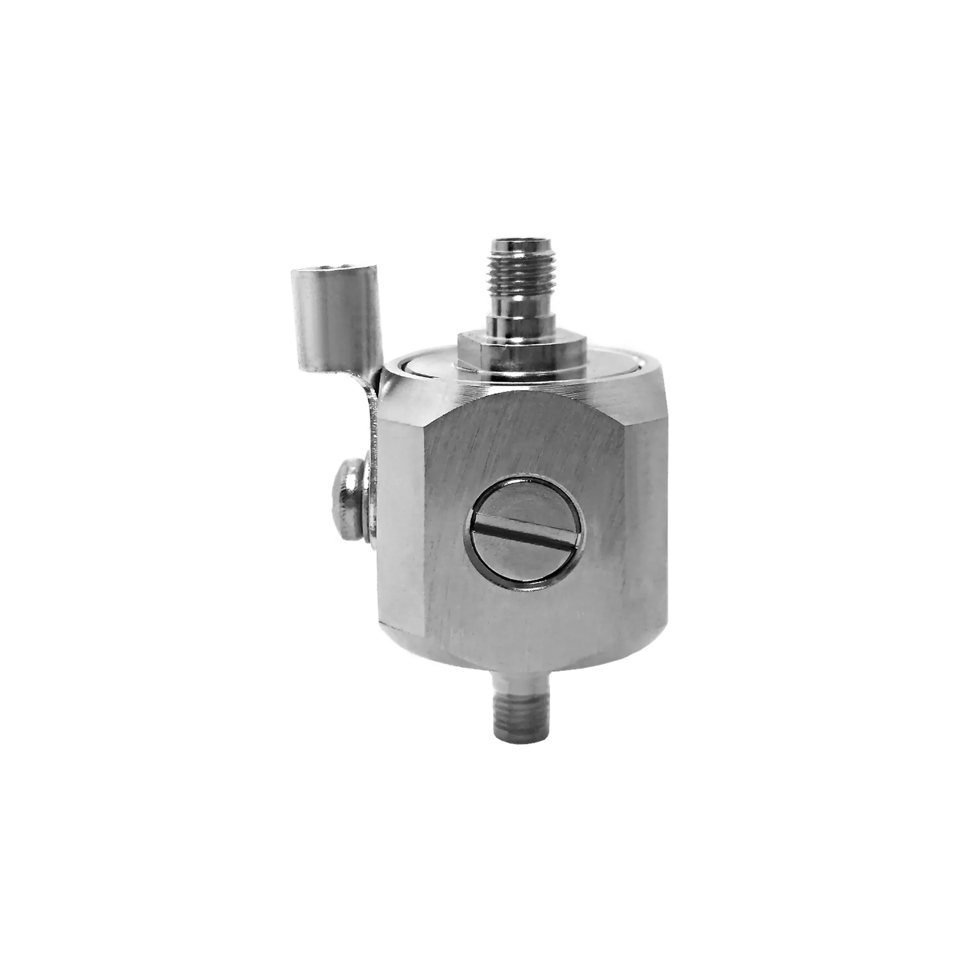
Radio frequency signals passing through a modern electronic system rely heavily on the transition point between printed circuit board traces and coaxial cable assemblies. The SMA female connector serves as this primary gateway, acting as a standardized 50-ohm interface on high-frequency PCBs, equipment enclosures, and test fixtures. Selecting the ideal mechanical mounting style ensures low transmission loss, prevents trace lifting under physical strain, and optimizes automated assembly yields across production runs.
Engineering teams must weigh frequency demands against mechanical stress and enclosure limits. Deploying an end launch SMA component on a high-speed microwave circuit provides ultra-clean signal paths, whereas choosing a through hole SMA connector offers structural durability for high-mating-cycle test gear. Understanding these mounting tradeoffs helps designers select the optimal PCB mount SMA fitting for every hardware iteration.
Choosing the proper connector footprint directly dictates high-frequency electrical performance and physical durability.
| Mounting Configuration | Max Frequency Limit | Typical Insertion Loss | Mechanical Retention | Primary Application Area |
|---|---|---|---|---|
| End Launch SMA | DC to 18 GHz | ~0.1 dB @ 10 GHz | Moderate | Microwave PCBs, VNA calibration, high-speed digital |
| Through Hole SMA | DC to 12 GHz | ~0.2 dB @ 10 GHz | Strong | Industrial IoT, bench equipment, production lines |
| Bulkhead Female Connector | DC to 18 GHz | ~0.3 dB (with pigtail) | Very Strong | Weatherproof enclosures, outdoor panels, rack gear |
| Surface Mount (SMD) | DC to 6 GHz | ~0.25 dB @ 6 GHz | Low to Moderate | High-density automated surface-mount assembly |
Matching these physical profiles to high-frequency board layouts prevents signal reflections caused by impedance discontinuities.
An end launch SMA receptacle mounts directly along the edge of a circuit board. The center pin lays flat against the top signal trace, while ground legs clamp or solder onto the top and bottom ground planes.
Because the center pin transits smoothly onto a microstrip line or grounded coplanar waveguide, an end launch SMA fitting eliminates vertical via transitions. This avoids via stub capacitance and parasitic inductance that degrade signals at gigahertz frequencies. For microwave applications operating above six gigahertz, high-frequency end launch launchers maintain low Voltage Standing Wave Ratio (VSWR) values up to eighteen gigahertz, making them the preferred choice for radar systems, satellite telemetry, and high-speed digital testing fixtures.
While edge-launch designs excel at microwave frequencies, applications subjected to frequent cable mating demand greater physical anchoring. A through hole SMA connector features mechanical ground pins that extend through plated circuit board holes to solder on the reverse side.
This through-hole anchoring absorbs severe lateral leverage when technicians attach and detach heavy test cables. Even though the vertical pin transit creates minor parasitic inductance—limiting optimal performance to around twelve gigahertz—the robust through hole SMA design prevents board trace lifting, making it ideal for rugged industrial equipment, field instruments, and high-volume commercial electronics.
When printed circuit boards sit deep within weather-sealed or EMI-shielded chassis, bringing high-frequency signals directly to an external panel requires decoupling mechanical strain from the circuit board entirely. An sma female bulkhead connector mounts directly into an enclosure cutout, secured by a threaded hex nut and lock washer.
A short coaxial jumper or internal micro-coax pigtail bridges the panel-mounted sma female bulkhead connector to an internal PCB mount SMA jack. This arrangement transfers heavy external cable tension, torque, and environmental vibration to the chassis wall rather than delicate solder pads. Incorporating O-ring seals on the bulkhead body allows outdoor wireless access points and marine communications systems to maintain strict ingress protection standards without compromising signal integrity.
Engineers designing a handheld spectrum analyzer needed an RF input jack capable of enduring over five thousand field mating cycles without performance loss or board fracture.
An early prototype utilizing a standard surface-mount fitting suffered solder pad cracking under severe cable twisting. By transitioning to a heavy-duty through hole SMA connector reinforced with secondary board anchoring, the mechanical strain was transferred into the PCB ground planes. Lifecycle testing confirmed that the revised assembly maintained a clean VSWR below 1.15:1 at six gigahertz across thousands of connection cycles, proving the value of through-hole mechanical anchoring in portable field equipment.
Ensuring low insertion loss and long mechanical life requires disciplined PCB layout and handling standards:
Delivering dependable high-frequency interconnects requires tight CNC machining tolerances, premium contact plating, and rigorous RF testing protocols. Microscopic defects on internal contact pins or imprecise dielectric dimensions cause return loss spikes that disrupt sensitive RF communication chains.
Worldpeak meets these demanding hardware standards through automated precision machining, advanced contact plating, and complete RF characterization testing. Supplying a comprehensive range of sma female connector configurations, high-frequency end launch SMA launchers, rugged through hole SMA components, flexible PCB mount SMA receptacles, and IP-rated sma female bulkhead connector assemblies, Worldpeak utilizes premium materials including gold-plated beryllium copper center contacts and stainless steel or passivated brass bodies.
Every Worldpeak connector undergoes rigorous testing to guarantee VSWR ratings below 1.15:1 across designated operating bands. Whether developing next-generation 5G infrastructure, building rugged aerospace systems, or sourcing high-volume industrial interconnects, partnering with an established manufacturer like Worldpeak ensures long-term signal clarity, thermal durability, and supply chain consistency.

2026/09/24
Choose a 7 16 connector for high-power RF: compare DIN and Type N, protect PIM margin, and apply field installation checks.

2026/09/24
Compare TNC connector types, specs and applications, including RP-TNC, bulkhead options, vibration performance and adapter selection.

2026/09/24
Understand MMCX connector basics, RF limits, and how to choose the right coaxial interface for compact systems.

2026/09/24
Understand RP-SMA connector polarity, mating rules, frequency checks, and OEM termination options for reliable RF builds.

2026/09/24
Choose the right bnc male connector for RF, CCTV and test systems with clear 50Ω vs 75Ω, type and installation guidance.

2026/09/24
Compare LMR400 specs, cable loss, uses, connectors and RG8/RG213 alternatives with a practical RF loss-budget method.