 EN
EN

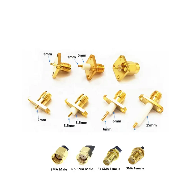
High-frequency signal routing within sub-6 GHz and millimeter-wave designs demands physical interconnects that maintain shielding effectiveness while minimizing return loss. A standard sma male interface is a sub-miniature 50-ohm connector utilizing a 1/4-36 UNEF-2B threaded coupling mechanism. Unlike slide-on or snap-on interfaces, this threaded architecture provides high axial contact retention, preventing center pin displacement and contact resistance fluctuations under high-vibration environments.
In precision RF links, the internal interface dimensions of an sma male connector are governed by international standards such as MIL-STD-348B. The outer conductor mating face relies on a solid polytetrafluoroethylene (PTFE) dielectric support, housing a gold-plated beryllium copper center pin that protrudes past the reference plane.
📐 The Coaxial Characteristic Impedance Formula
The characteristic impedance (Z₀) of the coaxial interface is mathematically defined by the ratio of the outer conductor's inner diameter (D) to the inner conductor's outer diameter (d), along with the relative permittivity of the dielectric medium (εᵣ):
Z₀ = (138 / √εᵣ) * log₁₀(D/d)
Any physical deformation of the outer shell, or an off-center pin alignment, shifts these precise mechanical dimensions (D/d). This geometric shift causes a localized impedance mismatch, resulting in high voltage standing wave ratio (VSWR) spikes and phase distortion at higher frequencies.
Polarity Safety and Avoiding Mechanical Pin Damage
One of the most frequent installation errors in wireless networking, cellular base stations, and laboratory setups is confusing standard sma male connectors with reverse-polarity (RP-SMA) variants.
⚠️ WARNING: Polar Mating Trap
Standard sma male connectors contain internal threads with a protruding center contact pin. An RP-SMA male, however, utilizes the exact same threaded outer coupling nut but houses a recessed female center socket inside. If an installer attempts to force a standard sma male connector onto an RP-SMA female jack (which also contains a male contact pin), the two pins will collide. This mechanical collision causes pin recession, bends the contact elements, and ruins both interfaces, necessitating immediate replacement of the jumper cable or instrument port.
-
Standard SMA Male: Threaded outer nut with a protruding center male pin. Mates with standard SMA female (external threads with a center contact socket).
-
RP-SMA Male: Threaded outer nut with a recessed center contact socket. Mates with RP-SMA female (external threads with a center contact pin).
-
Interference Penalty: Forcing incompatible polarities destroys the gold plating on the center contact, generating intermittent connection drops, high return loss, and physical hardware damage.
Structural Integration and Chassis Pass-Through Design
When routing RF signals from an enclosed, shielded module to an external antenna, maintaining electromagnetic shielding and environmental sealing is critical. A precision-machined sma male bulkhead connector provides a reliable pass-through interface, bridging internal microstrip boards and external cabling.
⚙️ Technical Blueprint: Bulkhead Mounting Parameters
-
Chassis Cutout Geometry: Standard D-flat or double D-flat profile. This flat edge prevents the bulkhead body from spinning within the panel when torque is applied to the external mating nut.
-
Hermetic and Environmental Sealing: Rear-mount silicone O-rings provide IP67/IP68 dust and moisture protection. High-vacuum applications often utilize glass-to-metal hermetically sealed bulkhead designs.
-
Panel Grounding: Direct metal-to-metal contact with the shielded enclosure wall is required. Any non-conductive paint or anodized layer must be removed around the mounting hole to prevent ground loop noise.
For benchtop test setups or back-to-back instrument routing, a solid male to male sma connector adapter serves as a critical utility. A high-frequency male to male sma connector allows engineers to directly couple adjacent female ports without introducing long cable runs. Every inline adapter adds a small discontinuity, so using a precision stainless-steel male to male sma connector with a VSWR rating below 1.15:1 is essential for maintaining calibration accuracy up to 18 GHz.
Connector Material Metallurgy and Torque Specifications
The mechanical durability and mating life cycle of high-frequency interconnects depend heavily on base metal metallurgy and coupling nut torque. Choosing between brass and stainless steel bodies involves balancing cost, environmental exposure, and the expected number of mating cycles.
📌 Material and Plating Specifications
-
Stainless Steel Body (Passivated or Gold-Plated): Typically specified for aerospace, military, and high-end laboratory test equipment. It offers high mechanical wear resistance, sustaining over 500 mating cycles without physical thread deformation.
-
Brass Body (Gold-Plated or Nickel-Plated): Widely utilized in commercial telecommunications, cellular modules, and consumer IoT hardware. It provides an excellent cost-to-performance ratio for fixed installations with limited mating cycles.
-
Beryllium Copper Contact Pin: Gold-plated center pins ensure low contact resistance and prevent galvanic corrosion when mated with different female sockets.
🔧 Proper Torque Management
Because the mechanical contact force determines high-frequency electrical performance, using a calibrated torque wrench is mandatory for consistent assembly.
-
Brass SMA Connectors: Recommend a mating torque of 0.35 to 0.60 Nm (3 to 5 in-lbs). Over-tightening brass can strip the threads or distort the internal PTFE dielectric.
-
Stainless Steel SMA Connectors: Recommend a mating torque of 0.80 to 1.10 Nm (7 to 10 in-lbs). Under-tightening stainless steel leads to air gaps at the reference plane, causing severe phase instability.
Cable Termination Methods for Custom Assembly Lines
To ensure consistent performance up to 18 GHz, termination methods must match the specific cable structure. Professional cable assembly lines employ strict preparation steps:
🛠️ Crimp-Style Termination
A crimp-style sma male connector is highly efficient for flexible cables like LMR-195 or RG-58. The center contact pin is crimped with a precise pin die or soldered to the conductor, while the outer brass ferrule is crimped over the braided shield. Automated stripping machines are recommended to prevent nicking the fine braid wires, which can reduce shielding effectiveness and introduce return loss spikes.
🛠️ Solder-Type (Direct Solder) Termination
For semi-rigid, hand-conformable, or low-loss corrugated cables (such as .086 or .141 semi-rigid lines), direct soldering is the standard method. The cable outer shield is soldered directly to the rear connector body, and the center contact is soldered to the core wire. Precise temperature control is required; excessive heat can cause the PTFE dielectric to swell, displacing the center pin and causing impedance discontinuities.
Following assembly, every high-frequency cable terminated with an sma male plug must undergo dual-port vector network analyzer (VNA) sweeping to verify return loss, insertion loss, and phase tracking before installation.
Precision Manufacturing and Worldpeak Global Supply Chain Capabilities
Reliable high-frequency signal transmission requires components manufactured to precise tolerances. Sourcing custom RF cable jumpers, PCB edge launchers, and bulkheads requires an experienced partner capable of maintaining strict dimensional tolerances, consistent plating quality, and full material traceability.
Worldpeak provides comprehensive manufacturing, engineering development, and global OEM supply chain support for high-precision coaxial systems. Operating high-precision multi-axis Swiss CNC turning machines, Worldpeak manufactures high-durability sma male plugs, custom male to male sma connector adapters, hermetically sealed sma male bulkhead connector assemblies, and custom coaxial jumpers.
Worldpeak enforces strict incoming material controls, utilizing certified non-magnetic stainless steel, high-purity brass, and premium beryllium copper. All contact pins receive a minimum of 30 micro-inches of gold plating over nickel barriers to ensure stable conductivity and reliable performance over 500 mating cycles. Adhering to ISO 9001 quality management systems, Worldpeak performs 100% vector network analyzer screening up to 40 GHz on precision lines. From rapid prototype sampling for aerospace designs to high-volume production for telecommunications platforms, Worldpeak provides reliable engineering, fast delivery, and robust supply chain services worldwide.





