 EN
EN

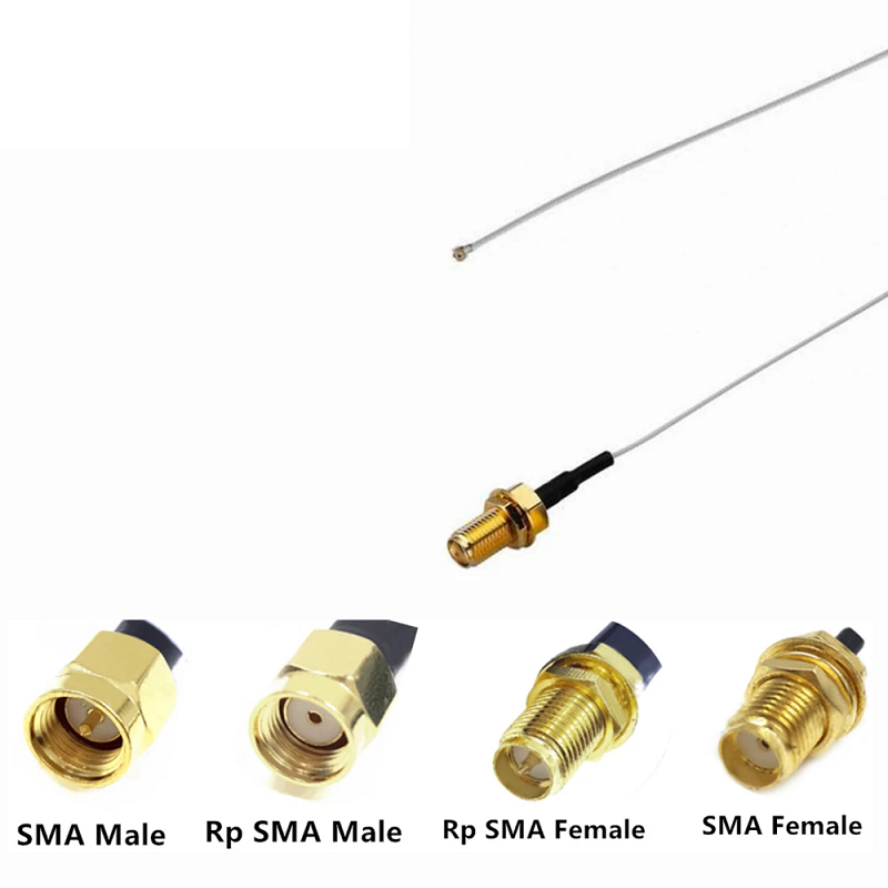
When an internal radio board, receiver filter, modular enclosure, or RF test point requires a short, flexible interconnect, using a reliable sma connector cable is often the most practical hardware solution. An SMA pigtail assembly shifts the threaded RF interface away from a crowded printed circuit board, allowing the outer enclosure wall to carry mechanical mating stress while providing technicians with a serviceable link rather than a delicate, direct-soldered board connection.
Selecting the right pigtail involves far more than picking a arbitrary cable length off the shelf. Cable construction, connector interface styles, gender configurations, mounting choices, bend pathways, and electrical testing parameters all directly influence link performance.
Treating pigtail selection as a system integration task ensures stable signal transmission. A proper procurement drawing should always define both mating interfaces, the coaxial cable family, the precise routing path, and the required test band. This disciplined approach makes an sma connector cable far easier to quote, install, inspect, and replace without disturbing the broader RF architecture.
Mechanical Advantages of Internal SMA Cable Pigtails
An SMA pigtail is a factory-terminated coaxial assembly typically routed from an internal PCB launch to a chassis bulkhead, antenna connector, or adjacent RF enclosure. Its primary value in modern hardware design lies in mechanical decoupling:
-
Board Stress Relief: A chassis-mounted connector absorbs repeated mating forces instead of transferring mechanical strain to a fragile board layout.
-
Service Accessibility: External bulkheads allow field technicians to connect or replace antennas without opening sealed equipment enclosures.
-
Packaging Flexibility: Flexible coaxial jumpers route smoothly around thermal heatsinks, shielding cans, and internal battery compartments where rigid trace layouts cannot go.
Even on short internal runs, electrical performance remains critical. At higher operating frequencies, insertion loss, return loss, and phase stability depend directly on cable construction, crimp termination quality, and minimum bend radii.
Selecting Coaxial Cables Before Finalizing Route Length
Define internal cable pathways with the equipment enclosure fully assembled. Measure the actual physical path rather than a straight-line distance, leaving sufficient slack to respect the minimum bend radius specified by the cable manufacturer. Forcing a tight bend near a crimp ferrule or solder joint alters local impedance and introduces a potential mechanical failure point under continuous vibration.
Flexible micro-coax is ideal for ultra-compact enclosures, whereas conformable or semi-rigid cable types are better suited when the cable path must maintain a fixed shape inside the chassis. Published frequency limits illustrate why cable selection matters: semi-rigid 0.085-inch or 0.141-inch lines often operate through 18 GHz, whereas standard flexible lines generally top out around 12.4 GHz.
To prevent procurement confusion, specify the following parameters on purchasing documentation:
-
Nominal characteristic impedance (typically 50 ohms for SMA systems)
-
Cable family, outer diameter, jacket material, and flexibility rating
-
Finished electrical length with allowable dimensional tolerances
-
Frequency range along with required insertion loss or VSWR limits
-
Connector style at each end (straight, right-angle, or bulkhead)
Verifying SMA Gender and PCB Interface Configurations
Connector terminology can easily cause confusion if pin configurations are not verified prior to ordering. In standard SMA conventions, a plug features an internal coupling nut with a center male pin, whereas a jack features external threads with a female socket contact. Reverse-Polarity (RP-SMA) interfaces swap these contacts and must be specified as a distinct hardware decision.
When terminating an sma cable connector at a chassis panel, designers usually specify an sma bulkhead connector. Always verify panel thickness, cutout dimensions, O-ring sealing options, lock-washer orientation, and thread clearance.
If the internal side connects directly to a circuit board, determine whether the layout requires an end-launch, vertical mount, or edge-mount sma connector pcb header. PCB launch geometry forms part of the high-frequency RF transition zone, meaning generic pad layouts should never replace the manufacturer's recommended land pattern.
When specifying an sma bulkhead connector, ensure sufficient thread length to accommodate the full panel stack-up and lock washer without putting strain on the rear cable ferrule.
Comparing SMA with Alternative Coaxial Interfaces
| Interface Family | Common Application Context | Primary Mechanical Advantage |
| SMA | Compact 50-ohm boards, RF modules, test equipment | Compact threaded coupling with wide 0–18 GHz availability |
| N-Type | Outdoor cellular towers, heavy jumper runs | Durable mechanical body with room for larger low-loss coax |
| BNC | Test benches, video equipment, low-frequency lines | Quick-connect bayonet mechanism for fast mating cycles |
| TNC | High-vibration aerospace and vehicular systems | Threaded coupling mechanism offering stronger retention than BNC |
These interface contexts serve as general selection guidelines rather than automatic frequency ratings. Always cross-reference system impedance, mechanical compatibility, environmental sealing, and supplier datasheets before finalizing hardware specifications.
Installation Guidelines and Quality Inspection Checklist
Follow these core practices during field installation and factory assembly:
-
Inspect Prior to Mating: Check center pins, threads, dielectrics, and braid exits for debris, burrs, or physical damage.
-
Hand-Start Coupling Nuts: Always engage threads by hand first; cross-threading degrades precision mating surfaces before electrical testing even begins.
-
Apply Calibrated Torque: Follow published torque limits—typically 3–5 in-lbs for brass SMA hardware and 7–10 in-lbs for stainless steel variants.
-
Provide Cable Strain Relief: Secure the coaxial line using cable ties or clamps wherever vibration or external movement could stress the connector backshell.
-
Sweep Test the Completed Assembly: Verify DC continuity and insulation resistance first, then perform RF return loss (VSWR) and insertion loss measurements across the full operational band.
Defining Complete Pigtail Specifications
Releasing a purchase order for a generic "SMA cable" leaves critical parameters unmanaged. Always specify both connector ends, coaxial cable types, overall finished lengths, operating frequency bands, panel mounting hardware, and required test documentation.
Worldpeak provides precision-engineered RF hardware including the standard sma connector cable, high-frequency sma cable connector components, right-angle sma connector pcb headers, and sealed sma bulkhead connector options engineered for seamless equipment integration. Supported by automated assembly lines, rigorous network analyzer testing, and dependable global B2B delivery schedules, Worldpeak supports custom prototyping as well as high-volume production builds.
When reviewing engineering drawings, treat every sma connector cable as a complete, fully tested assembly with defined mechanical and electrical boundaries. That disciplined approach ensures your short RF pigtails perform dependably across every deployment.
Frequently Asked Questions
What is the main difference between standard SMA and RP-SMA connectors?
Standard SMA male plugs feature a center pin and internal threads, while female jacks feature a center socket and external threads. RP-SMA reverses the center contacts: the male plug carries a socket contact, and the female jack carries a center pin.
Why is an SMA bulkhead connector preferred for enclosure designs?
An sma bulkhead connector mounts directly to the equipment panel, transferring mechanical strain away from internal PCB traces while providing an external IP-rated or RF-shielded connection point.
How do I choose the correct SMA connector PCB footprint?
Select the footprint based on operational frequency and board stack-up. Utilize edge-launch or end-launch connectors for high-frequency signal paths to minimize impedance discontinuities at the board transition zone.





