 EN
EN

What environmental resistance can be customized for OEM rf cable
2026/09/25
Customize an rf high frequency cable for temperature, moisture, corrosion, vibration, flexing, and OEM validation needs.
2026/09/09
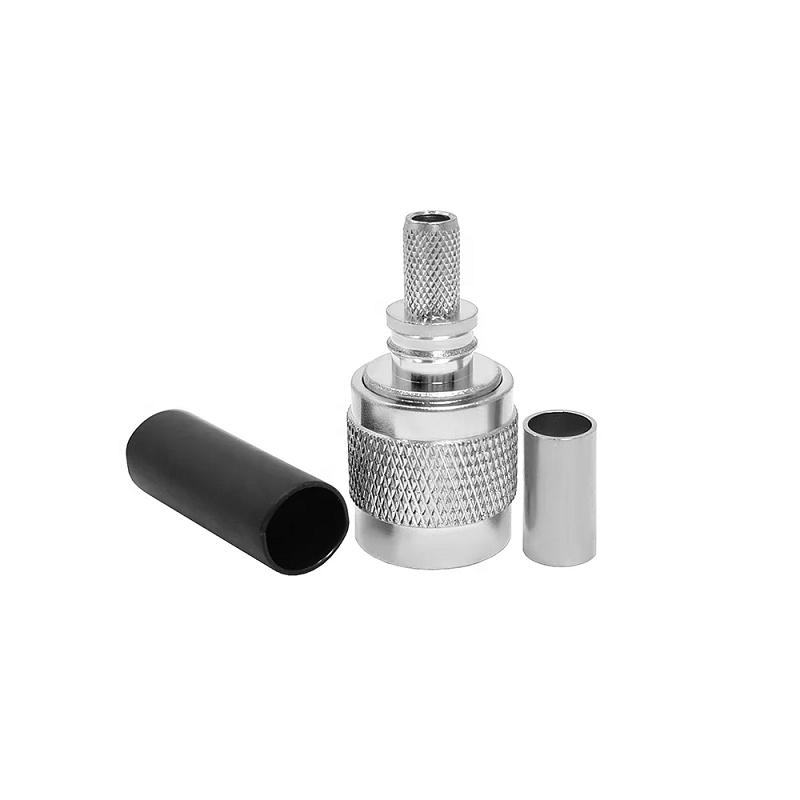
RF systems frequently require bridging different interface styles without compromising signal integrity or introducing unwanted return loss. Connecting equipment equipped with threaded coupling ports to quick-disconnect bayonet feedlines demands a reliable coaxial adapter. Selecting an optimal tnc to bnc connector solution involves looking closely at characteristic impedance, operational bandwidth, mechanical thread stability, and surface plating quality. Understanding structural differences and specific use cases—such as comparing high-frequency RF connector conversion against lower-frequency bnc to banana connector test leads—ensures system setups operate smoothly across demanding test and field environments.
Understanding why a TNC BNC adapter becomes necessary starts with examining how each connector type handles mechanical strain and high-frequency signal propagation. Both interfaces share similar internal center conductor dimensions, but their coupling mechanisms set them apart.
Deploying a precision tnc to bnc connector allows test gear, field antennas, and monitoring receivers with mismatched front panels to mate directly while maintaining consistent 50-ohm characteristic impedance across common operational bands.
Different equipment layouts and housing enclosures demand specific gender combinations and mounting profiles to prevent physical stress on front-panel jacks.
| Adapter Configuration | Typical System Role | Key Mechanical Feature |
|---|---|---|
| TNC Male to BNC Female | Links TNC antenna ports to BNC test leads | Threaded outer plug to quick-twist socket |
| TNC Female to BNC Male | Connects BNC equipment ports to TNC cables | Threaded outer jack to bayonet plug |
| Bulkhead Feedthrough Adapter | Routes RF paths through enclosure panels | O-ring sealed rear mount with locking nut |
| Right-Angle (90°) Adapter | Handles tight clearance inside instrument racks | Low-profile elbow housing to prevent cable kinks |
Selecting the right gender format avoids stack-up errors and eliminates the need for chaining multiple inline connectors, which can degrade overall return loss.
While a tnc to bnc connector manages high-frequency RF connector conversion, adapting BNC test points for low-frequency instruments requires a completely different approach. A bnc to banana connector bridges coaxial outputs to dual binding posts or banana plug inputs on multimeters, power supplies, and low-frequency oscilloscopes.
Unlike high-frequency coaxial lines where impedance matching remains paramount, a bnc to banana connector focuses on low contact resistance and high current handling. Quality adapters feature gold-plated beryllium copper spring contacts capable of enduring thousands of insertion cycles while keeping signal degradation negligible across DC and audio-frequency measurements.
Long-term measurement accuracy depends directly on structural material quality and internal machining precision. Substandard die-cast housings or thin contact plating lead to early surface oxidation, elevated VSWR, and intermittent signal connectivity.
Checking these material indicators ensures chosen adapters remain stable across repeated lab mating cycles and harsh field environments.
A telecom field engineering team required an efficient solution for interfacing roof-mounted TNC vehicle antennas with compact BNC-input spectrum analyzers during drive-test coverage audits. The installation called for a durable TNC BNC adapter capable of withstanding vehicle vibration without introducing signal loss or phase noise across LTE and 5G mid-band frequencies.
Deploying high-precision TNC male to BNC female units featuring PTFE dielectrics and passivated brass housings resolved the interface mismatch cleanly. The adaptation maintained insertion loss below 0.12 dB at 2.6 GHz, delivering stable signal monitoring performance throughout extensive road testing.
Achieving repeatable performance across diverse test and measurement programs requires strict batch-to-batch machining consistency and complete factory inspection testing. Inconsistent thread machining or off-center socket pins cause intermittent electrical contacts and elevated return loss at microwave frequencies.
WORLDPEAK supports critical RF infrastructure and test bench operations by manufacturing precision-engineered tnc to bnc connector solutions, custom TNC BNC adapter fittings, versatile bnc to banana connector leads, and high-frequency coaxial adapter options. Utilizing multi-axis Swiss-type CNC lathes, automated plating setups, and automated testing equipment, WORLDPEAK ensures every adapter delivers exact dimensional alignment and stable impedance. Complete VSWR and insertion loss validation across every production lot provides reliable quality and long-term durability for telecom operators, defense contractors, and electronics labs worldwide.

2026/09/25
Customize an rf high frequency cable for temperature, moisture, corrosion, vibration, flexing, and OEM validation needs.

2026/09/25
Streamline RF equipment assembly lines with custom coaxial jumpers. Reduce line-side rework, ensure precise routing, and boost production efficiency.

2026/09/25
Learn PL-259 connector selection, soldering, weatherproofing, and RF applications for dependable antenna feedlines.

2026/09/25
Confirm impedance for a 90 degree coax connector with an ODM test plan covering VNA setup, VSWR, acceptance criteria, and release records.

2026/09/25
Learn when an n type coax connector can omit extra anti-corrosion treatment and when OEM exposure conditions require it.

2026/09/25
Learn how the custom cable and wire sample process helps ODM buyers validate design, testing, and production readiness.