 EN
EN

What environmental resistance can be customized for OEM rf cable
2026/09/25
Customize an rf high frequency cable for temperature, moisture, corrosion, vibration, flexing, and OEM validation needs.
2026/09/08
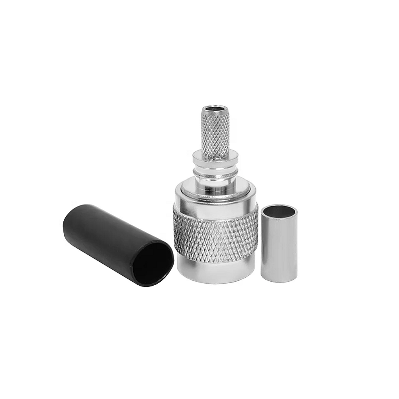
RF engineers and field technicians regularly encounter system designs that mix different coaxial connector standards. Connecting heavy-duty outdoor cabling to dense internal circuit boards requires bridging different physical interfaces without ruining signal integrity. The TNC to SMA adapter serves as an essential bridge between robust outdoor cabling and high-frequency miniature electronics.
Combining two popular threaded connector designs, a TNC SMA adapter creates a secure electrical and mechanical interface across telecom, military, and aerospace equipment. Knowing how to choose the right TNC to SMA adapter or SMA to TNC adapter combination helps prevent costly impedance mismatches, signal attenuation, and mechanical failures in the field.
A successful connection depends on understanding the fundamental physical differences between each threaded RF connector interface. While both standards maintain a nominal 50-ohm characteristic impedance, their mechanical dimensions demand precise internal tapering inside every adapter body.
Operating frequency limits represent one of the most critical aspects of RF adapter compatibility. Placing an adapter into a coaxial transmission path introduces an electrical discontinuity. The overall bandwidth of any adapter assembly defaults to the maximum operating limit of its lowest-rated interface.
Standard TNC connectors operate effectively up to 11 GHz, while precision TNC variants extend up to 18 GHz. Standard SMA connectors operate efficiently up to 18 GHz, with high-frequency precision designs pushing up to 26.5 GHz or higher. Therefore, installing a standard TNC to SMA adapter restricts the overall link performance to 11 GHz.
Attempting to run a standard TNC SMA adapter past its 11 GHz rating generates severe impedance mismatches, elevating the Voltage Standing Wave Ratio (VSWR) and causing high insertion loss. For high-frequency microwave projects operating above 11 GHz, precision TNC interfaces featuring air dielectrics or specialized PTFE support structures preserve electrical symmetry and keep reflection coefficient levels within spec.
| Interface Parameter | Standard TNC Connector | Standard SMA Connector | TNC to SMA Adapter Unit |
|---|---|---|---|
| Thread Type | 5/8-24 UNEF | 1/4-36 UNS | Dual-Thread Hybrid |
| Max Frequency (Standard) | 11 GHz | 18 GHz | 11 GHz |
| Max Frequency (Precision) | 18 GHz | 26.5 GHz | 18 GHz |
| Center Pin Diameter | 0.062 inches | 0.050 inches | Precision-Stepped Transition |
| Coupling Mechanism | Heavy Threaded | Fine Threaded | Threaded / Dual-Interface |
| Primary Use Case | External / Rugged Cabling | Internal / High-Density Board | System Interconnection |
Vibration resistance and environmental durability make threaded RF connector designs superior to push-on or bayonet-style connectors in high-reliability applications. Bayonet connectors can micro-bounce under extreme mechanical vibration, causing phase jitter and intermittent signal dropout. In contrast, the continuous thread engagement of a TNC SMA adapter locks mating faces together under constant mechanical force.
Military ground vehicles often illustrate real-world RF adapter compatibility challenges. Vehicle armor enclosures demand thick, weather-sealed bulkhead entries using ruggedized TNC cabling to withstand weather exposure and branch strikes. Inside the cabin, compact software-defined radios and signal processors rely on space-saving SMA jack interfaces.
Installing a bulkhead-mounted TNC to SMA adapter provides a rugged exterior TNC connection while breaking out into a flexible SMA jumper harness inside the electronics bay. Specifying gold-plated contacts and low-loss PTFE dielectrics ensures minimal attenuation across extreme operating temperatures ranging from -40 degrees Celsius up to +85 degrees Celsius.
Proper installation technique matters just as much as hardware quality:
Maintaining tight tolerances across complex TNC to SMA adapter production requires advanced CNC machining and automated testing workflows. Minor dimensional variations inside the internal impedance step can transform an otherwise clean adapter into a high-loss barrier.
Leading coaxial equipment manufacturers like WORLDPEAK support global RF projects with precision-engineered TNC to SMA adapter configurations. Offering straight and right-angle designs with custom plating options—including gold, nickel, and tri-metal alloys—WORLDPEAK ensures high mechanical durability and low reflection coefficients. Every SMA to TNC adapter undergoes 100 percent automated vector network analyzer testing for VSWR, insertion loss, and insulation resistance prior to dispatch, giving system integrators peace of mind across telecommunications, defense, and aerospace installations worldwide.

2026/09/25
Customize an rf high frequency cable for temperature, moisture, corrosion, vibration, flexing, and OEM validation needs.

2026/09/25
Streamline RF equipment assembly lines with custom coaxial jumpers. Reduce line-side rework, ensure precise routing, and boost production efficiency.

2026/09/25
Learn PL-259 connector selection, soldering, weatherproofing, and RF applications for dependable antenna feedlines.

2026/09/25
Confirm impedance for a 90 degree coax connector with an ODM test plan covering VNA setup, VSWR, acceptance criteria, and release records.

2026/09/25
Learn when an n type coax connector can omit extra anti-corrosion treatment and when OEM exposure conditions require it.

2026/09/25
Learn how the custom cable and wire sample process helps ODM buyers validate design, testing, and production readiness.