 EN
EN

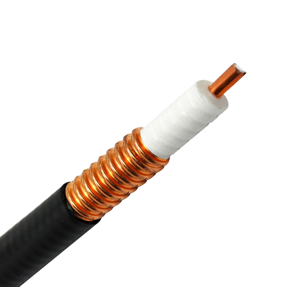
In telecommunications and mission-critical radio networks, signal integrity hinges on the quality of the transmission line between active radio transceivers and antennas. An underground feeder cable provides the shielded, controlled-impedance pathway required to route radio frequency energy beneath ground level, inside conduits, or across subterranean utility corridors. Unlike general utility wiring, RF transmission requires strict impedance matching, minimal dielectric absorption, high shielding effectiveness, and extreme environmental durability. Selecting the right transmission media ensures that link budgets remain predictable throughout decades of exposure to soil moisture, mechanical stress, and thermal cycling.
Clarifying RF Coaxial Lines and Electrical Power Feeders
Sourcing confusion frequently occurs when field specifications cross between power distribution and radio frequency systems. In commercial generator installations and electrical distribution panels, contractors routinely specify power links such as a 4 0 feeder cable or a 2 0 feeder cable to carry high-amperage alternating current. Similarly, mobile broadcasting trailers, temporary power skids, and industrial backup plants frequently rely on a camlock feeder cable assembly equipped with single-pin locking connectors for rapid power distribution.
A high-performance RF underground feeder cable serves a completely different engineering purpose. While a 4 0 feeder cable or 2 0 feeder cable is sized strictly according to copper conductor cross-section, ampacity, and heat dissipation under 50 Hz or 60 Hz electrical loads, an RF underground feeder cable is designed around wave propagation, 50-ohm characteristic impedance, skin effect, and velocity of propagation. Deploying a camlock feeder cable provides heavy electrical current to base station rectifiers, but the RF signal itself demands precision coaxial transmission lines to avoid catastrophic mismatch loss.
| Engineering Parameter | RF Underground Feeder Cable | Power Distribution Feeders (2 0 / 4 0) | Temporary Power Links (Camlock) |
|---|---|---|---|
| Primary Function | Low-loss 50-ohm RF wave transmission | High-current AC/DC power transmission | Portable or temporary high-amperage power feed |
| Common Industry Terms | Corrugated copper feeder, 7/8 in, 1-5/8 in | 2 0 feeder cable, 4 0 feeder cable, Class B/C | Camlock feeder cable, single-conductor power cable |
| Critical Performance Metric | Attenuation (dB/100m), VSWR, PIM | Ampacity (A), voltage drop, circular mils | Quick-disconnect cycle life, contact resistance |
| Typical Operating Range | 100 MHz to 6 GHz | 50 Hz / 60 Hz (up to 600V or 1000V) | 50 Hz / 60 Hz industrial supply (up to 400A) |
| Termination Interface | 4.3-10, 7/16 DIN, N-Type, EIA Flange | Mechanical lugs, compression crimps | Single-pole cam-style locking connectors |
Selecting Feeder Diameters for Link Budget Integrity
Choosing the correct underground feeder cable diameter requires balancing insertion loss, pathway geometry, and mechanical handling limits. As cable outer diameter increases, signal attenuation decreases significantly due to the larger surface area of the inner and outer conductors. However, larger cables require wider trench radii, heavier support clamps, and specialized termination tools.
When planning trench routes, macro-cell installations typically deploy 7/8-inch or 1-5/8-inch corrugated copper lines for long trunk spans, while transitioning to 1/2-inch superflexible jumpers near cabinet entries. Running an underground feeder cable through buried conduit requires verifying that the total route attenuation does not exceed link budget margins at the highest operational frequency.
| Cable Configuration | Outer Diameter | Minimum Bending Radius | Typical Loss at 900 MHz | Primary Application |
|---|---|---|---|---|
| 1/2 in Superflexible | ~13.5 mm | 32 mm (single bend) | ~6.8 dB / 100 m | Cabinet jumpers, tight conduit entries, DAS drops |
| 7/8 in Corrugated | ~27.8 mm | 120 mm (single bend) | ~3.7 dB / 100 m | Macro-cell runs, sub-grade building entries, trunk lines |
| 1-5/8 in Corrugated | ~50.0 mm | 200 mm (single bend) | ~2.1 dB / 100 m | High-power broadcast, long underground duct runs |
Direct Burial and Conduit Installation Procedures
Subterranean feeder pathways expose coaxial structures to lateral compression, ground movement, and standing water. Installing an underground feeder cable directly in soil is acceptable only when the outer jacket is explicitly rated for direct burial with high-density polyethylene (HDPE). In industrial and municipal projects, placing cables inside rigid Schedule 40 or Schedule 80 PVC conduits provides far superior long-term mechanical protection.
Trench layouts must account for separation from electrical infrastructure. Running an RF underground feeder cable parallel to a 4 0 feeder cable or 2 0 feeder cable inside the same utility duct risks inductive coupling and physical jacket degradation from electrical thermal rise. Separate ducts or trench compartments should always be maintained.
| Installation Phase | Key Engineering Requirement | Critical Pitfall to Avoid |
|---|---|---|
| Pathway Preparation | Install smooth-wall HDPE or PVC ducting with pull mandrels | Leaving sharp burrs, gravel, or construction debris in duct |
| Pulling Mechanics | Use break-away pulling eyes calibrated to cable tension limits | Pulling directly on pre-installed RF connectors |
| Bend Management | Maintain continuous sweeping curves above minimum bend limits | Creating sharp kinks that permanently alter 50-ohm impedance |
| Duct Sealing | Apply mechanical duct plugs and expanding closed-cell foam | Allowing underground conduit to become a subterranean drainage pipe |
Environmental Sealing and Grounding Protocols
Moisture ingress is the primary cause of catastrophic failure in outdoor and buried coaxial systems. A microscopic pinhole in a weatherseal allows water to migrate through the outer corrugated conductor via capillary action, rapidly degrading VSWR and introducing severe passive intermodulation (PIM). Every outdoor interface along an underground feeder cable run requires multi-layered environmental protection.
Grounding kits must be installed at strategic intervals to divert lightning surges before lines transition underground. Grounding contact plates must match the metallurgy of the outer conductor to eliminate galvanic corrosion.
| Protection Layer | Material Specification | Installation Method |
|---|---|---|
| Primary Seal | Heavy-duty butyl mastic sealing compound | Wrap opposing the water-run direction with 50% overlap |
| Secondary Barrier | Premium all-weather vinyl electrical tape | Apply two layers under tension to compress the butyl mastic |
| UV & Physical Armor | UV-resistant outer wrap or cold-shrink EPDM sleeve | Slide over mated interface and collapse evenly over cable jacket |
| Grounding Kit | Tinned copper strap with weatherproofing wrap | Bond to site ground ring before entry into the subterranean duct |
Commissioning Verification and Quality Acceptance
Before backfilling trenches or sealing conduit access vaults, rigorous acceptance testing ensures the underground feeder cable meets baseline design parameters. Testing should be documented across the entire operating spectrum of the radio system.
Line sweep testing isolates return loss and insertion loss anomalies. Distance-to-Fault (DTF) measurements verify that no internal conductor pinching occurred during cable pulling.
| Test Parameter | Acceptance Threshold | Diagnostic Meaning |
|---|---|---|
| Voltage Standing Wave Ratio (VSWR) |
≤
1.15:1 across operating band
|
Verifies impedance consistency and absence of physical deformation |
| Return Loss |
≥
23 dB across operating band
|
Confirms minimal reflected RF power back into the transmitter |
| Passive Intermodulation (PIM) |
≤
-160 dBc (2x20W carrier test)
|
Detects microscopic oxidation, loose interfaces, or material defects |
| Distance-to-Fault (DTF) | Uniform trace along cable length | Pinpoints exact physical location of localized pinching or moisture |
Sourcing Precision Assemblies Through Worldpeak
Deploying reliable subterranean RF transmission systems requires tight component tolerances, durable weather seals, and certified electrical performance. While civil contractors handle heavy power delivery using a 4 0 feeder cable, a 2 0 feeder cable, or an auxiliary camlock feeder cable for temporary grid hookups, the high-frequency RF transmission chain demands precision coaxial manufacturing.
Worldpeak delivers high-performance RF coaxial connectors, low-PIM jumper assemblies, and custom-engineered feeder cable terminations designed for challenging outdoor and underground operating environments. Operating advanced CNC production centers, automated stripping equipment, and rigorous network analyzer testing benches, Worldpeak provides precision 4.3-10, 7/16 DIN, and N-type assemblies tailored to strict mechanical and electrical specifications. From customized cut-to-length feeder runs to fully tested pre-terminated jumpers, Worldpeak supports global telecommunications operators, defense installations, and industrial system integrators with scalable OEM and ODM supply chain capabilities.





