 EN
EN

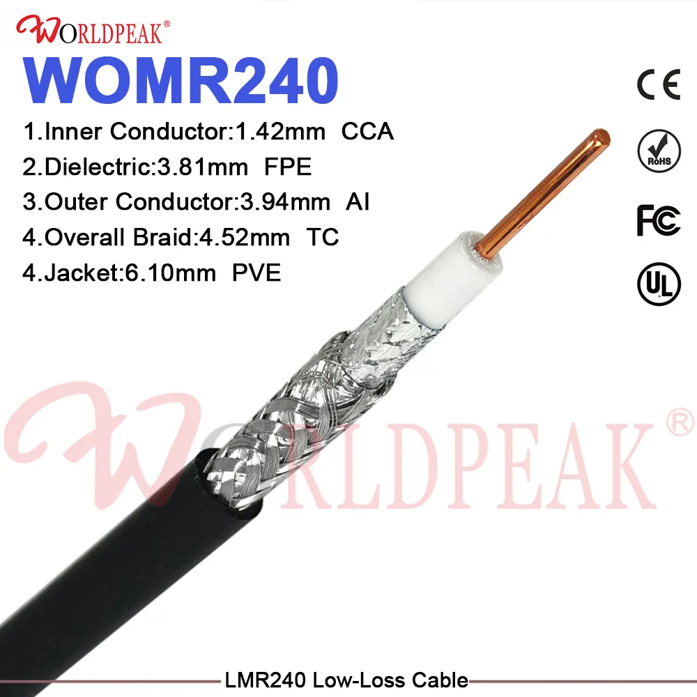
What Are the Key Specs of 50 Ohm Coaxial Jumper?
When you are specifying a 50 ohm coaxial jumper for an antenna feed, a base station port, or a laboratory bench connection, the impedance value on the label is only the starting point. The specs that determine whether a jumper will perform—or cause problems—go several layers deeper. Having worked on RF system integration projects across telecom infrastructure and lab environments, I have learned that selecting a cable assembly without looking past the impedance spec typically leads to rework. This article walks through the specifications that matter most, and why each one affects your system differently.
Why 50 Ohm? Understanding the Impedance Standard
The 50 ohm characteristic impedance is the global standard for RF and microwave transmission in commercial, industrial, and defense applications. It sits between the impedance that minimizes attenuation in an air-dielectric line (~77 ohms) and the impedance that maximizes power handling (~30 ohms). For most antenna systems, base station feeder cables, and lab test setups operating across HF through several GHz, 50 ohms gives acceptable loss, manageable power handling, and broad connector ecosystem support.
If your system uses 75 ohm interfaces—common in broadcast video—a 50 ohm coaxial jumper will introduce a mismatch at every connection point. Confirm the system impedance before selecting any cable assembly.
The Six Specifications That Determine Performance
1. Cable Type and Inner Conductor Configuration
The cable designation—RG58, RG8X, LMR400, RG174, or others—defines most of the electrical and mechanical properties of the jumper. Different types use different dielectric materials, conductor diameters, and shielding constructions, all of which affect the other specs on this list. Treating cable type as an interchangeable detail is one of the most common specification errors in RF procurement.
2. Insertion Loss and Attenuation Rate
Attenuation rate is the single most consequential electrical spec for any 50 ohm coaxial jumper used in a signal path. It is expressed in dB per unit length at a given frequency, and it climbs with frequency. For reference:
- RG58 50 ohm: approximately 13.1 dB per 100 feet at 750 MHz. Practical for short laboratory interconnects under 6 meters or mobile installations under 6 feet. At higher frequencies or longer runs, RG58 introduces signal degradation that erodes receiver sensitivity.
- RG-8X: approximately 10.95 dB per 100 feet at 750 MHz, with a smaller outer diameter than RG-8U. A useful mid-range option for moderate-distance field runs where bulk matters.
- LMR-400: approximately 3.5 dB per 100 feet at 750 MHz, and 0.223 dB per meter at 2.4 GHz. The preferred choice for base station feeder and long antenna cable runs where minimizing path loss is critical.
- RG-174: approximately 23.6 dB per 100 feet at 750 MHz. Very high loss, but also the thinnest and most flexible construction. Appropriate only for short pigtails under 0.5 meters in space-constrained applications.
A useful rule of thumb: doubling the cable length doubles the dB loss. For a 1-meter coaxial jumper at 2.4 GHz, loss alone can reach 1.46 dB or more—roughly 30% of signal energy—depending on cable type. That loss compounds with every connector in the path.
3. Frequency Range
Every cable type has a rated maximum operating frequency, which is determined by the dielectric and conductor geometry. A 50 ohm coaxial jumper used in a system operating above its rated frequency will show rapidly increasing attenuation and potential mode degradation. For systems operating above 3 GHz, LMR-series or equivalent low-loss cable types are strongly preferred over RG58 or RG8X constructions.
4. Connector Interface Type
Connector selection affects mechanical compatibility, frequency ceiling, and how reliably the mating cycle holds up over time. Common interfaces on 50 ohm jumpers include:
- SMA: rated to 18 GHz, compact, widely used in laboratory and base station applications. A 50 ohm SMA terminator is often added to unused ports in test setups to maintain system impedance and prevent reflections.
- 50 ohm BNC: rated to approximately 4 GHz, bayonet coupling for fast connect/disconnect cycles, common in test equipment and lower-frequency infrastructure.
- N-type: rated to 11 GHz, larger body, suitable for outdoor and feeder cable applications where weather resistance and mechanical durability are priorities.
- TNC, QMA, MCX: specialized interfaces for specific installation environments.
5. Shielding Coverage and Transfer Impedance
Shielding governs two things: the cable's immunity to external RF interference, and how well it isolates the transmitted signal from adjacent systems. Single-braid shields offer 85–95% coverage in standard builds. Double-braid or braid-plus-foil designs improve coverage to 98%+ and reduce transfer impedance, important in environments with strong adjacent RF sources—dense base station sites, lab benches with multiple signal generators, or railway installations near high-power traction systems.
6. Minimum Bend Radius
Bending a cable beyond its minimum bend radius causes permanent deformation of the dielectric and outer conductor, which increases impedance irregularities and insertion loss at the bend point. The bend radius limit scales roughly with cable diameter: LMR-400 specifies a minimum bend radius of approximately 25 mm, while RG-58 is more forgiving at around 12 mm. In tight routing paths—equipment rack cable management, antenna mast cable dressing, or instrument panel connections—selecting a cable type with an appropriate bend radius for the available space prevents a common installation failure mode.
Comparing Common 50 Ohm Cable Types
| Cable Type | OD (approx.) | Attenuation @ 750 MHz (dB/100ft) | Typical Application |
|---|---|---|---|
| RG-174 | 0.100" | ~23.6 | Short flexible pigtails, compact modules |
| RG58 50 ohm | 0.195" | ~13.1 | Lab bench, mobile/portable, short runs |
| RG-8X | 0.242" | ~10.95 | Moderate-distance field runs, amateur radio |
| LMR-400 | 0.405" | ~3.5 | Base station feeder, long antenna runs |
OEM and Custom-Length Options
Standard-length jumpers cover the majority of installation scenarios, but system integrators and equipment manufacturers frequently need non-standard lengths, mixed connector configurations, or specific jacket materials. Custom 50 ohm coaxial jumper assemblies allow exact routing without excess cable that adds bulk and loss at bends. For OEM procurement, factors to clarify include: required length tolerance, connector gender and interface type at each end, outer jacket material (PVC, TPE, or halogen-free for specific environments), and whether per-assembly insertion loss test data is required for incoming inspection.
Lead times for custom cable assemblies vary by cable type and volume. Sample quantities for prototype and qualification testing typically ship within one to two weeks from a manufacturer with in-house fabrication capability. Production volumes require longer lead time planning, particularly for assemblies using specialized jacket materials or tight-tolerance length matching for phase-sensitive applications.
Installation, Bending, and Weatherproofing Tips
- Connector torque: SMA connectors have a specified mating torque of approximately 0.9 N·m (8 in-lb). Hand-tightening without a torque wrench is a common cause of poor contact resistance and intermittent connections in base station and lab environments.
- Bend radius compliance: Route cables before securing, and verify that no bend point falls inside the manufacturer's minimum bend radius specification. A once-kinked cable does not recover its original performance.
- Weatherproofing at outdoor connections: For antenna and base station installations, connector interfaces exposed to weather require self-amalgamating tape, heat-shrink weatherproofing boots, or equivalent sealing to prevent moisture ingress. Even a small moisture path into the connector interface will degrade return loss and eventually cause corrosion-related failure.
- Unused port termination: Unused RF ports should be capped with a matched 50 ohm terminator—whether a 50 ohm BNC cap or a 50 ohm SMA terminator—to maintain system impedance and prevent interference pickup.
Related 50 Ohm Coaxial Cable Products
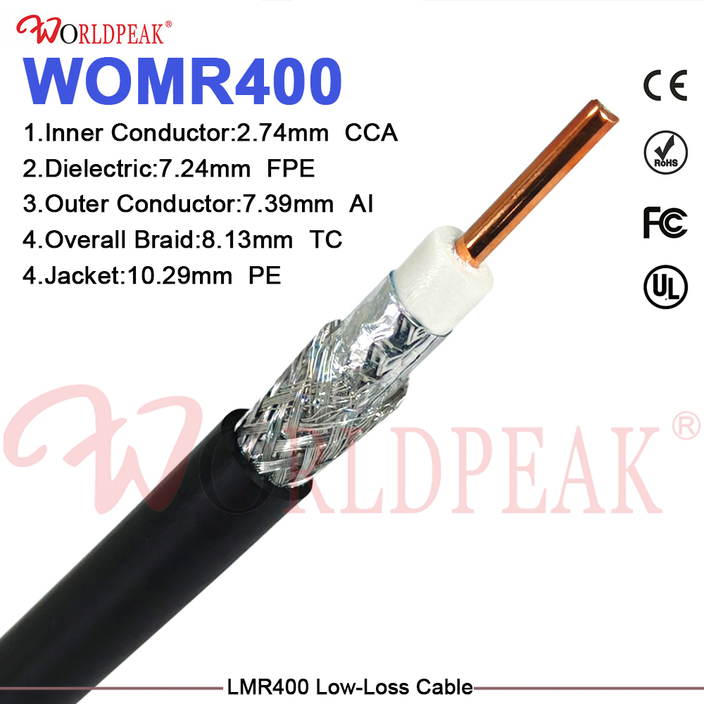
If you are sourcing cable assemblies for base station feeder or low-loss applications, the LMR400 Low-Loss 50 Ohm Coaxial Cable from Worldpeak provides the low-attenuation performance required for longer runs. For specialized laboratory or measurement applications requiring guarded coaxial construction, the TRC-50-2 Triaxial Cable - 50 ohm Guarded Coax adds an outer guard conductor for noise-sensitive measurement setups. For standard 50 ohm feeder cable with engineering data, see the Worldpeak RG196 50-Ohm Coaxial Cable: Engineering Data & Selection Guide.
Conclusion
Selecting a 50 ohm coaxial jumper requires evaluating cable type, attenuation rate, frequency range, connector interface, shielding, and bend radius together—not any single parameter in isolation. A cable that meets the impedance and connector spec but is over-length for the application or under-specified on attenuation will still degrade system performance. Understanding these six dimensions and how they interact is what separates a specification that works in the field from one that looks correct on paper.





