 EN
EN

7/16 DIN Connector Guide: High-Power RF Standard
2026/09/24
Choose a 7 16 connector for high-power RF: compare DIN and Type N, protect PIM margin, and apply field installation checks.
2026/09/01
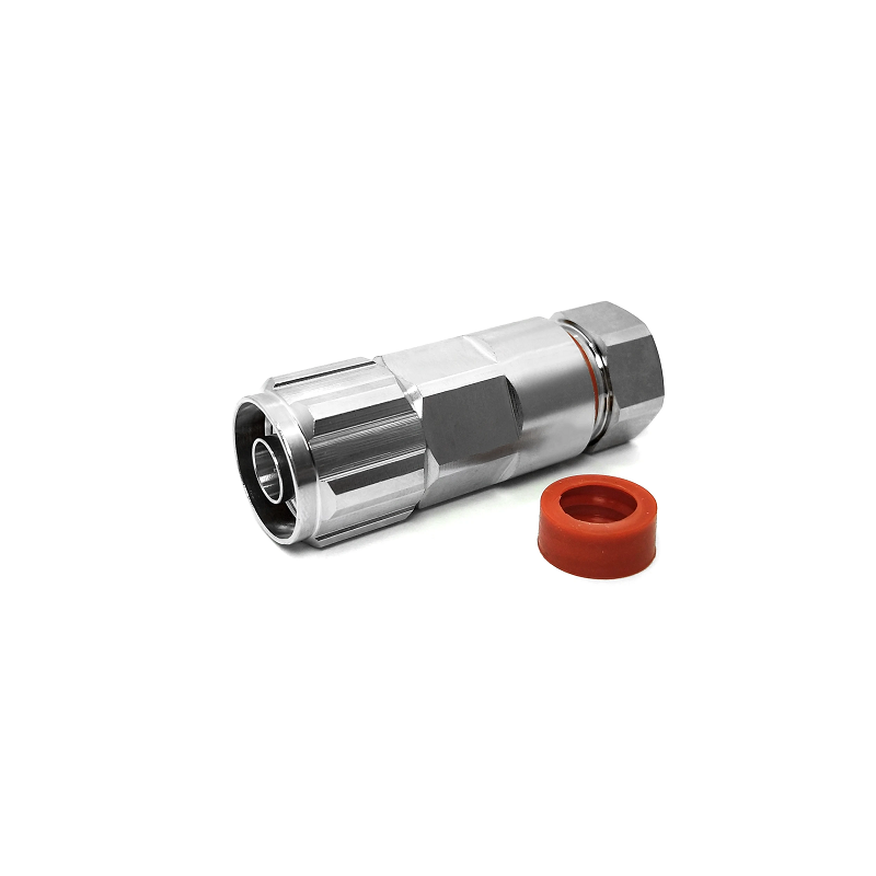
Selecting the right RF component often feels straightforward until thermal expansion, moisture ingress, or impedance mismatches derail system performance. Among the standard workhorses in high-frequency engineering, the type n connector female stands out as a baseline standard across telecommunications, aerospace, and test environments. Engineered to hold tight 50-ohm impedance across demanding frequency bands, this coaxial interface bridges the gap between rugged field durability and laboratory-grade signal integrity.
Whether assembling outdoor cellular infrastructure or designing complex panel layouts, understanding core RF connector specs helps prevent costly field failures. Here is a comprehensive breakdown of mechanical standards, material trade-offs, and design factors—focusing closely on the n female bulkhead connector for panel-mount applications.
Electrical consistency forms the bedrock of high-frequency design. When evaluating an N type female interface, engineers usually focus on three core parameters: impedance control, standing wave ratio, and signal attenuation.
Voltage Standing Wave Ratio (VSWR) directly indicates how much RF power reflects back into the transmission line. A poorly fitted internal socket or subpar plating can quickly ruin system efficiency. High-performance design targets vary depending on the operational frequency:
Commercial Infrastructure (DC to 6 GHz): Typical VSWR target remains under 1.30:1. Ideal for basic cellular base stations and Wi-Fi networks.
Industrial Telecom & Broadcast (6 to 11 GHz): Target stays below 1.25:1 to handle higher data throughput with minimal signal degradation.
Precision & Defense Equipment (11 to 18 GHz): Tight tolerances require VSWR under 1.20:1 to maintain signal fidelity across test instruments and radar systems.
Achieving low reflection requires strict mechanical control over the air gap between the outer shield and the inner conductor. Even a micron-level mismatch in center contact positioning can skew high-frequency performance.
Insertion loss measures overall attenuation as signals pass through the interface. A quality type n connector female maintains an insertion loss of roughly 0.05 to 0.15 dB at 3 GHz, rising slightly up to 0.4 dB as frequencies approach 18 GHz.
Power handling capability hinges on heat dissipation within the internal dielectric. Under continuous transmit power, thermal energy must pass through the dielectric out to the outer metallic body. If the internal conductive contacts degrade, contact resistance increases, leading to localized heating and potential thermal breakdown.
Durability in the field depends entirely on what lies under the surface plating. A reliable type n connector female balances electrical conductivity with long-term mechanical resilience.
The female center contact acts as a slotted socket that accepts the solid male pin. Repeated mating cycles can cause traditional spring metals to lose tension, increasing contact resistance over time.
Beryllium Copper (BeCu): The industry gold standard for socket contacts. Offers high tensile strength, excellent spring retention, and high conductivity.
Phosphor Bronze: A budget-friendly alternative suited for commercial applications with minimal mating cycles.
Plating Standards: To prevent oxidation and ensure smooth mating, high-grade center sockets feature direct gold plating over a nickel underlayer (minimum 1.27 microns of gold on primary mating surfaces).
The insulating dielectric holds the center conductor in place while maintaining precise spacing relative to the outer wall. Different materials trade off frequency limit against manufacturing cost:
Virgin PTFE (Teflon): Provides a low dielectric constant (2.1) and handles temperature ranges from -65°C to +165°C. Serves as the primary dielectric for applications up to 18 GHz.
Glass-Filled PTFE: Increases mechanical strength and elevates high-end temperature stability up to +200°C, ideal for high-vibration automotive or military environments.
PEI and PEEK: Offer superior mechanical toughness for extreme physical stresses, though higher dielectric constants require careful internal geometry adjustments.
When designing enclosures, instrument chassis, or weatherproof outdoor cabinets, direct cable connections are rarely practical. This is where the specialized n female bulkhead connector plays a vital role.
Connecting heavy coax cables directly to internal circuit boards invites structural mechanical failure. Using a bulkhead connector transfers physical bending stress, cable pull, and vibration directly into the cabinet frame rather than the fragile internal electronics.
A panel-mounted n female bulkhead connector creates a continuous 360-degree metallic ground contact with the enclosure wall. This grounding minimizes stray electromagnetic interference (EMI) leakage and protects sensitive internal circuitry.
For outdoor infrastructure, these components incorporate integrated silicone O-rings and passivated stainless-steel mounting hardware. An IP67 rating ensures dust-tight protection and prevents water ingress under heavy rainfall or submersion scenarios.
Even high-precision RF connector specs cannot overcome improper assembly techniques in the field. Adhering to simple mechanical guidelines extends operational lifespan significantly.
The standard threaded interface uses a 5/8-24 UNEF thread profile. Hand-tightening often leaves small mechanical gaps, leading to intermittent signal dropouts and elevated VSWR. Conversely, applying excessive force deforms the internal PTFE insulation and damages the socket spring fingers.
Using a dedicated torque wrench calibrated to 0.7–1.1 N-m ensures optimal metallic contact without risking internal deformation.
Before installation, inspecting the inner contact area under magnification prevents widespread system contamination. Pitted plating, metal shavings, or misaligned pin sockets degrade conductivity and introduce passive intermodulation (PIM) issues—a common pain point in modern 5G networks.
Sourcing high-performance coaxial components requires balancing strict quality control against production scalability. For demanding projects requiring commercial, industrial, or precision-grade N type female hardware, working with experienced manufacturing partners is critical.
Companies like Worldpeak focus on high-precision manufacturing processes, utilizing advanced CNC machining, rigorous plating controls, and automated assembly to deliver consistent impedance matching across vast production batches. Every n female bulkhead connector option manufactured by Worldpeak undergoes comprehensive 100% VSWR sweep testing prior to shipment, ensuring field-ready reliability for outdoor base stations, broadcast facilities, and laboratory equipment.
By prioritizing precise geometric control, robust contact plating, and correct dielectric selection, RF engineers can confidently specify a type n connector female that withstands harsh environmental conditions while delivering uncompromised signal performance.

2026/09/24
Choose a 7 16 connector for high-power RF: compare DIN and Type N, protect PIM margin, and apply field installation checks.

2026/09/24
Compare TNC connector types, specs and applications, including RP-TNC, bulkhead options, vibration performance and adapter selection.

2026/09/24
Understand MMCX connector basics, RF limits, and how to choose the right coaxial interface for compact systems.

2026/09/24
Understand RP-SMA connector polarity, mating rules, frequency checks, and OEM termination options for reliable RF builds.

2026/09/24
Choose the right bnc male connector for RF, CCTV and test systems with clear 50Ω vs 75Ω, type and installation guidance.

2026/09/24
Compare LMR400 specs, cable loss, uses, connectors and RG8/RG213 alternatives with a practical RF loss-budget method.