 EN
EN

7/16 DIN Connector Guide: High-Power RF Standard
2026/09/24
Choose a 7 16 connector for high-power RF: compare DIN and Type N, protect PIM margin, and apply field installation checks.
2026/09/08
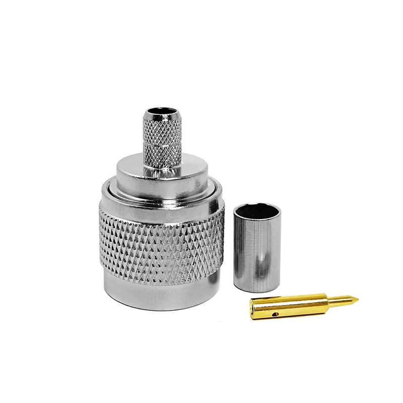
Engineers and network installers frequently face signal loss, poor impedance matching, or sudden system downtime caused by sub‑par RF interconnects. Among the vast array of coaxial interfaces, this threaded coaxial component stands out as a foundational piece for broadcast networks, wireless base stations, and test benches. Designed in the 1940s by Paul Neill, the N‑type system remains popular due to its threaded coupling mechanism, rugged metal build, and dependable performance from DC up to 11 GHz (or 18 GHz in precision‑grade models).
However, sourcing reliably manufactured coaxial transition hardware requires looking beyond basic physical dimensions. Choosing the wrong internal pin tolerances, plating materials, or impedance ratings can quickly disrupt high‑frequency systems.
Matching interconnects across diverse RF devices demands a clear understanding of interface styles. Common setups include same‑series connections and cross‑series transitions to SMA, BNC, TNC, or 7‑16 DIN interfaces.
Selecting high‑grade coaxial transition hardware involves evaluating core electrical, mechanical, and material specifications:
Deploying this coaxial hardware outdoors requires weatherized features like internal O‑rings and IP‑rated sealing to protect against moisture ingress. Tower‑mounted equipment and outdoor base stations need corrosion‑resistant shells that withstand temperature swings and rain exposure. Condensation trapped inside poorly sealed assemblies will gradually erode contact surfaces and trigger intermittent faults that prove difficult to reproduce during routine troubleshooting.
In laboratory environments, measurement repeatability takes top priority. Precision units feature air dielectric structures and gold‑plated center contacts. These components endure over 500 mating cycles without performance degradation, delivering accurate baseline calibration for spectrum analyzers and vector network analyzers. Metrology‑grade assemblies demand careful handling; physical dents, contamination, or over‑torqued couplings will invalidate calibration references and skew all subsequent measurement readouts.
Consistent performance relies on strict manufacturing controls. Dependable suppliers verify every production batch using vector network analyzers, providing traceable VSWR plots, insertion loss measurements, and material certifications. Industry standards like ISO 9001, RoHS, and CE reflect rigorous quality control throughout machining, plating, and final assembly. Reputable manufacturers document raw material lots, plating thickness metrics, and electrical test logs, enabling traceability should field‑unit anomalies emerge after installation.
WORLDPEAK supports global telecommunication and test applications with precision‑machined interconnect solutions. Offering a wide range of products—including barrel couplers, bulkhead feed‑through units, and custom cross‑series transitions—WORLDPEAK ensures 100% electrical testing and robust quality control for demanding RF networks worldwide.

2026/09/24
Choose a 7 16 connector for high-power RF: compare DIN and Type N, protect PIM margin, and apply field installation checks.

2026/09/24
Compare TNC connector types, specs and applications, including RP-TNC, bulkhead options, vibration performance and adapter selection.

2026/09/24
Understand MMCX connector basics, RF limits, and how to choose the right coaxial interface for compact systems.

2026/09/24
Understand RP-SMA connector polarity, mating rules, frequency checks, and OEM termination options for reliable RF builds.

2026/09/24
Choose the right bnc male connector for RF, CCTV and test systems with clear 50Ω vs 75Ω, type and installation guidance.

2026/09/24
Compare LMR400 specs, cable loss, uses, connectors and RG8/RG213 alternatives with a practical RF loss-budget method.