 EN
EN

7/16 DIN Connector Guide: High-Power RF Standard
2026/09/24
Choose a 7 16 connector for high-power RF: compare DIN and Type N, protect PIM margin, and apply field installation checks.
2026/09/02
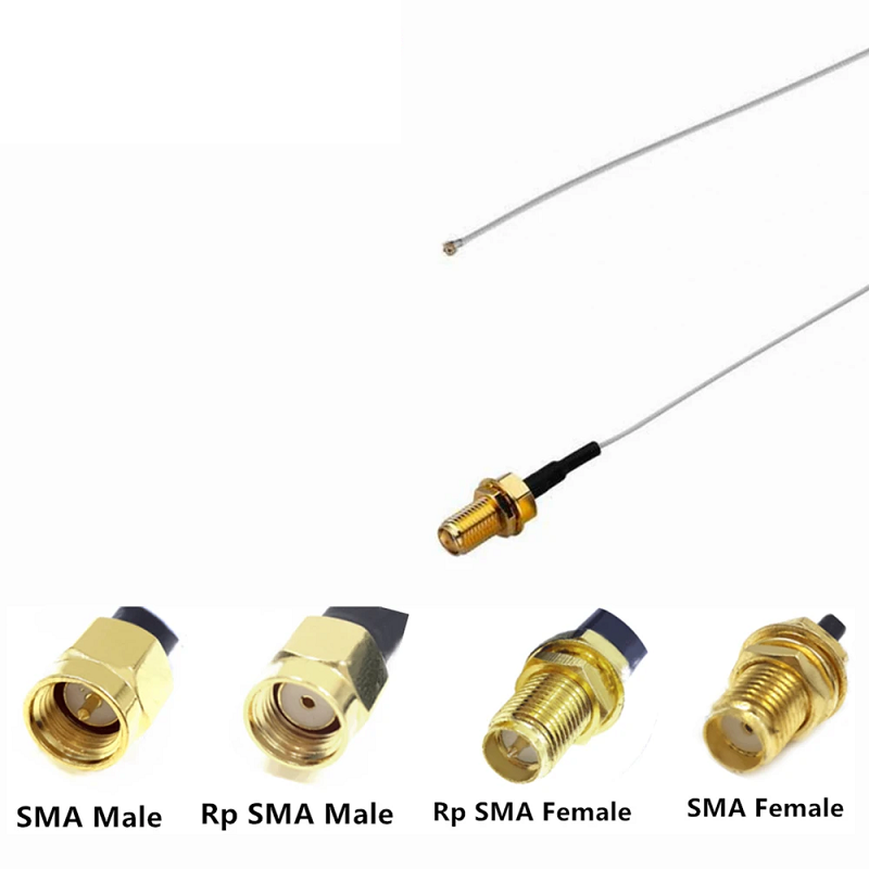
When building high‑frequency circuits, setting up wireless networks, or wiring signal test setups, picking the right interface hardware saves endless troubleshooting later. Among the vast family of microwave connectors, the female sma connector—often referred to in technical schematics as an SMA jack—remains an absolute cornerstone of modern electronics. From high‑speed printed circuit boards to field‑deployed Wi‑Fi access points, these compact components deliver stable 50‑ohm impedance across demanding frequency ranges.
However, selecting an SMA jack involves much more than just picking a part off a shelf. You have to account for key factors like frequency upper bounds, PCB launch geometries, plating durability, and gender polarity. Misunderstanding the difference between a standard interface and a reverse polarity SMA port can stall an entire installation or permanently destroy delicate pins.
Whether you are designing custom wireless gateways or sourcing replacement hardware for benchtop instruments, this RF connector buying guide walks through every critical metric you need to review before placing an order.
Engineered under military standards like MIL‑STD‑348 and international specs like IEC 60169‑15, the standard female sma connector features external 1/4‑36 UNF threads and a central dielectric sleeve housing a female contact socket. It mates with a standard male SMA plug, which features internal threads and a protruding center pin.
In RF engineering, the term SMA jack specifically refers to this female‑threaded, socket‑style configuration. Standard commercial variants deliver clean signal performance from DC up to 18 GHz, while high‑precision, air‑dielectric versions extend performance clear up to 26.5 GHz or 27 GHz.
Core physical attributes include:
By far the most common mistake when sourcing an RF connector buying guide hardware list is confusing a standard socket with an rp sma female interface.
The reverse polarity SMA specification was created to satisfy FCC regulations (specifically FCC Part 15 rules) for consumer wireless equipment. The goal was to prevent end‑users from easily attaching non‑compliant, high‑gain external antennas to home Wi‑Fi routers and access points.
Here is how the structural layout changes between the two:
Because an rp sma female housing retains the exact same 1/4‑36 outer thread geometry as a standard SMA jack, they will physically screw together with mismatched plugs. However, forcing mismatched genders together leads to immediate hardware failure:
To choose the optimal SMA jack for your application, balance the mechanical layout with your system's electrical requirements.
How the connector attaches to your PCB or enclosure directly influences both mechanical strength and RF impedance:
Cheap metal alloys ruin high‑frequency performance and wear out quickly. Look for high‑spec materials when evaluating hardware:
| Component Part | Recommended Material | Performance Benefit |
|---|---|---|
| Center Contact | Beryllium Copper (BeCu) | Excellent elastic memory, holding tight pin grip over 500+ cycles. |
| Body Shell | Machined Brass or Stainless Steel | Stainless steel resists severe weather; brass provides cost‑effective durability. |
| Plating Finish | Gold over Nickel (min 1.27 µm) | Prevents oxidation and minimizes contact resistance across high frequencies. |
| Dielectric | Solid Virgin PTFE (Teflon) | Delivers stable dielectric constant and high temperature resistance during soldering. |
The electrical performance of an SMA jack depends heavily on machining tolerances and internal insulator design. The table below outlines typical electrical targets across different application grades.
| Performance Grade | Frequency Range | Max VSWR Target | Primary Application Area |
|---|---|---|---|
| Commercial Grade | DC to 6 GHz | Less than 1.25:1 | Consumer Wi‑Fi, IoT, and cellular antennas |
| Industrial Grade | DC to 12.4 GHz | Less than 1.20:1 | Avionics, marine radar, and base stations |
| Precision Grade | DC to 18 GHz | Less than 1.15:1 | Benchtop test equipment and lab analyzers |
| Metrology Grade | DC to 26.5 GHz | Less than 1.08:1 | Precision RF calibration standards |
When specifying hardware for systems operating above 6 GHz, always request full VSWR and insertion loss sweep test data to verify signal integrity before bulk production.
Even top‑quality hardware can underperform if improperly handled during assembly and field deployment.
Applying too much torque to a female sma connector deforms the internal PTFE insulator and pushes the center contact out of alignment. This causes severe impedance dips and spikes VSWR. Always use a calibrated 8 in‑lb (0.9 Nm) torque wrench when securing SMA interfaces.
Connecting heavy coaxial cables directly to a panel‑mounted SMA jack puts excessive strain on the solder joint or thin PCB trace. Always incorporate strain relief boots or clamp‑style bulkhead adapters to absorb mechanical tugs.
Dust, metal shavings, or bent pins inside an rp sma female socket can destroy delicate mating pins on test cables. Inspect interfaces under magnification and clean contacts with compressed air and optical‑grade isopropyl alcohol before connecting.
Building high‑performance RF setups requires choosing reliable, precision‑engineered hardware. Worldpeak supplies a complete range of high‑frequency interconnect solutions, including standard female sma connector options and specialized rp sma female configurations engineered to exact global standards. By using gold‑plated beryllium copper contacts, heavy‑duty brass shells, and high‑grade PTFE dielectrics, Worldpeak helps engineering teams build low‑loss RF links across wireless, telecom, and test setups. Every batch undergoes rigorous 100% testing for continuity and VSWR performance, ensuring consistent signal transfer even in challenging operating environments.

2026/09/24
Choose a 7 16 connector for high-power RF: compare DIN and Type N, protect PIM margin, and apply field installation checks.

2026/09/24
Compare TNC connector types, specs and applications, including RP-TNC, bulkhead options, vibration performance and adapter selection.

2026/09/24
Understand MMCX connector basics, RF limits, and how to choose the right coaxial interface for compact systems.

2026/09/24
Understand RP-SMA connector polarity, mating rules, frequency checks, and OEM termination options for reliable RF builds.

2026/09/24
Choose the right bnc male connector for RF, CCTV and test systems with clear 50Ω vs 75Ω, type and installation guidance.

2026/09/24
Compare LMR400 specs, cable loss, uses, connectors and RG8/RG213 alternatives with a practical RF loss-budget method.