 EN
EN

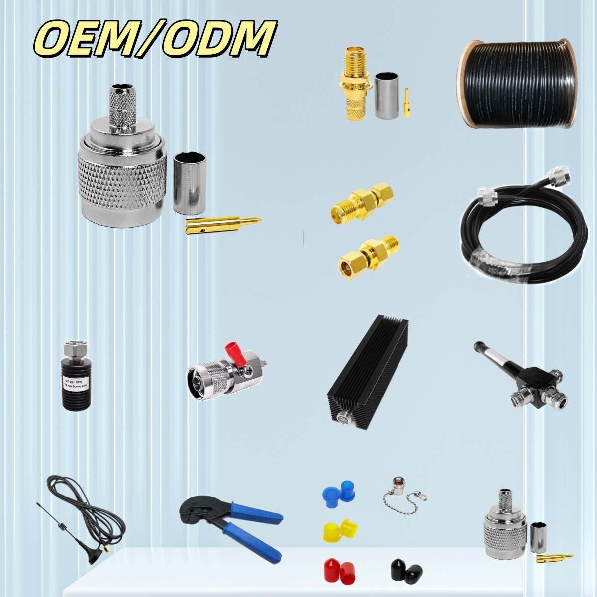
Why N Type Male Connector Matters in Professional RF Setups
Early in my work specifying connectors for outdoor antenna feeder runs and microwave backhaul links, I approached the n type male connector as just another item on a component list. That changed after a failed S-band installation where intermittent signal degradation traced back to a BNC connector pushed past its rated 4 GHz ceiling. The N-type was the correct answer the whole time — I had just not understood why it matters in a way that BNC and TNC cannot match at microwave frequencies.
The N Type Male Connector as the Microwave RF Standard
The n type male connector is a threaded, medium-size coaxial RF interface standardized under IEC 60169-16 and MIL-STD-348. The IEC standard specifies an outer conductor inner diameter of 7 mm — the precise geometry required to maintain 50 Ω characteristic impedance at microwave frequencies. Standard N-type connectors operate from DC to 11 GHz; extended-range configurations reach 18 GHz for C-band and Ku-band satellite and X-band radar work.
The threaded coupling mechanism distinguishes the N-type from push-pull interfaces. Threaded engagement holds consistent mating force across temperature cycles and vibration events — critical for tower-mounted feeders experiencing thousands of thermal cycles over service life. The gasket on the n type male connector body provides IP65-rated sealing when mated correctly to an N female interface, covering dust ingress and low-pressure water exposure.
N-Type Variants: Male, Female, Right-Angle, and Panel Mount
The N-type family covers more installation scenarios than the straight plug alone:
- N type male straight (plug): Standard cable termination for RG-8, RG-213, LMR-400, and similar cables. Crimp, clamp, and solder versions available. Quality straight configurations hold VSWR ≤ 1.3.
- N female (jack): Bulkhead and panel-mount variants for enclosure feedthroughs, instrument chassis, and antenna base plates.
- Right-angle N type male: For 90° routing transitions in rack equipment or tight cable harnesses. VSWR ceiling rises to ≤ 1.5 vs ≤ 1.3 for straight — a factor in link budget calculations above 6 GHz.
- Panel-mount and flange variants: For chassis integration requiring repeated mating cycles and mechanical stress resistance across service life.
It is intuitive to assume that a larger n type male connector should be tightened with more force than a smaller SMA. The actual torque specification for N-type is 1.36 N·m (12 in-lb) — over-torquing deforms the gasket and reduces IP sealing in subsequent matings. Using a calibrated torque wrench for N-type installation is a step I see skipped in the field more often than it should be.
N-Type vs TNC vs BNC: Frequency and Performance Comparison
When engineers compare alternatives to the n type male connector, TNC and BNC come up most often. They are not physically interchangeable, and the gaps in frequency range, power handling, and environmental protection determine which belongs in a given system:
| Connector | Frequency Range | Impedance | Environmental Protection |
|---|---|---|---|
| N-type male | DC–11 GHz (standard); up to 18 GHz | 50 Ω | IP65 gasketed mated pair |
| TNC | DC–11 GHz | 50 Ω | No environmental gasket |
| BNC | DC–4 GHz | 50 Ω or 75 Ω | No environmental sealing |
TNC matches N-type on frequency but lacks the IP-rated gasket. Indoor lab setups with frequent connection cycles are where TNC works well. Once the installation moves outdoors — feeder runs, enclosures subject to condensation, anything exposed — the N type male connector's environmental sealing is not worth trading away to reduce connector body size. BNC's 4 GHz ceiling means it is categorically unsuitable above L-band — a gap of roughly 7 GHz that spans LTE, 5G sub-6 GHz, and most satellite uplink bands.
High-Power Outdoor Applications: Impedance Matching and Weatherproofing
The 50 Ω characteristic impedance is maintained through the 7 mm outer conductor geometry. In high-power transmit paths, impedance discontinuities at connectors generate reflected power that reduces effective radiated power and stresses transmitter output stages. For continuous-wave operation at kilowatt levels common in broadcast, radar, and wireless infrastructure, connector geometry and material selection determine system reliability.
Systems bridging 7/16 DIN transmitter ports to N-type cable assemblies require connectors maintaining 50 Ω impedance through the transition. Products like the RFX-Custom-02 High-Power RF Connector (7/16 DIN Female to N Male, 3 kW @ 2.5 GHz) from Worldpeak illustrate where the n type male connector handles sustained kilowatt-level transmit paths at base station frequencies using silver-plated brass construction for conductivity and thermal performance.
One outdoor installation error I've seen repeatedly: selecting a connector housing based on its IP class without verifying that the mated pair sealing surface is undamaged. The IP65 rating belongs to the mated interface, not the housing alone. A deformed gasket or debris on the female seating surface eliminates the IP rating regardless of what the spec sheet states.
SMA-to-N Adapter Chains in Mixed-Interface Systems
Many professional RF setups combine SMA-ported instruments with N-type antenna infrastructure. The configurations required most often are the sma male to n type female adapter — connecting SMA-ported equipment to an N-type cable or antenna port — and the sma female to n type male adapter for the reverse direction. Both must maintain 50 Ω impedance through the adapter body to avoid accumulating VSWR across the signal path.
A n type male to male adapter (barrel adapter) joins two N female interfaces directly — useful when connecting an antenna feedthrough to an in-line surge protector or extending a feeder cable segment. Verify the adapter's frequency ceiling against your operating frequency: an adapter rated to 6 GHz limits the full chain to 6 GHz, regardless of what the cable or antenna connector can support.
Practical Selection Criteria for N Type Male Connectors
- Cable compatibility: Match termination style (crimp, clamp, solder) and ferrule size to cable outer conductor diameter. LMR-400 and RG-213 require different crimp ferrule sizes despite similar diameters.
- Frequency requirement: Standard N-type to 11 GHz covers most 5G sub-6 GHz and sub-microwave applications. Extended-range variants handle C-band and above.
- Power rating: Verify continuous and peak power handling at the operating frequency — kilowatt-class applications require specifically rated connector bodies.
- Environmental verification: Confirm IP65 applies to the mated pair. Inspect gaskets and seating surfaces before outdoor assembly.
- Torque compliance: 1.36 N·m (12 in-lb) is the typical N-type specification. Under-torquing causes intermittency; over-torquing deforms the gasket.
Worldpeak manufactures N-type male and female connectors, N-type adapters including sma male to n type female and sma female to n type male configurations, and high-power interface combinations across these application parameters. Pre-shipment insertion loss and VSWR sweep data ships with each order as part of the inspection documentation — a detail that matters when component traceability is part of the procurement requirement.





