EN
EN

43-10-female-to-43-10-female-lightning-arrester---dc---3-ghz, 43-10-female-to-43-10-female-lightning-arrester---dc---3-ghz, /rf-lightning-arrester
EN
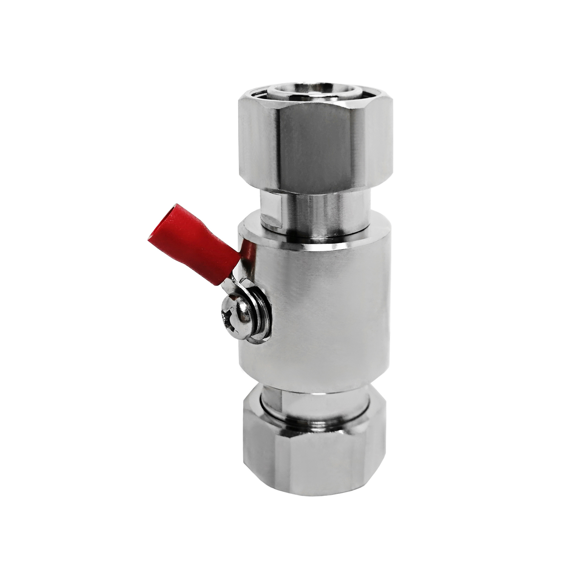
This 4.3-10 Female to 4.3-10 Female lightning arrester is a GDT based RF surge protector designed for DC - 3 GHz operation. It sits in the transmission line between the antenna and the radio equipment, diverting lightning-induced transients to ground before they reach the sensitive front end. The 50 ohm design holds insertion loss at 0.2 dB with a VSWR of 1.25 or better across the passband.
Request a Quote | Download Datasheet | Ask an Engineer
Product Overview
Designed for RF coaxial lines operating from DC to 3 GHz, this 4.3-10 Female to 4.3-10 Female lightning arrester provides an in-line path for surge protection between an antenna system and connected radio equipment. The 4.3-10 Female to 4.3-10 Female lightning arrester uses a replaceable 90 V gas discharge tube (GDT) with a stated 10 kA (8/20 us) surge-current capability. During normal service, the GDT remains high impedance so that RF energy passes through the transmission line with stated insertion loss of 0.2 dB. When a transient reaches the line, the GDT ionizes and diverts the surge energy through the grounding connection rather than toward sensitive equipment.
The GDT design supports a low-capacitance, low-loss signal path and allows the discharge tube to be replaced after a significant surge event. Compared with diode-based alternatives, its triggering threshold is higher, but that operating characteristic is appropriate for many antenna feeder and base-station line applications where low RF disturbance is important.
Protection Mechanism and Construction
Its compact 4.3-10 interface is suited to space-conscious, high-density base-station installations.
Reference Technical Specifications
The listed data describes the reference configuration of this 4.3-10 Female to 4.3-10 Female lightning arrester. Confirm final values against the selected production configuration before specifying the part for a project.
Parameter |
Specification |
Notes |
Connector Interface |
4.3-10 Female to 4.3-10 Female |
Standard RF connector |
Mounting Style |
Inline |
Body configuration |
Impedance |
50 ohm |
System impedance |
Frequency Range |
DC - 3 GHz |
Passband |
Insertion Loss |
0.2 dB |
Across passband |
VSWR |
1.25 |
Maximum |
Power Handling |
250 W |
CW, reference |
Discharge Element |
90 V |
Gas discharge tube |
Surge Current |
10 kA (8/20 us) |
8/20 us waveform |
Grounding |
Ring terminal |
M4 lug, ground wire |
Body Material |
Machined brass |
Corrosion-resistant plating |
Weight |
112.3 g |
Approximate |
Typical Application |
Panel entry, antenna port protection, DAS |
Primary use case |
Reference figures apply to this protection-product family and require confirmation against the final production version.
Engineering Comparison
Applications
Installation and Grounding Notes
OEM and B2B Support
FAQ
Q: When should the gas discharge tube be replaced?
A: The 90 V GDT is specified for 10 kA (8/20 us). Following a major surge, test the tube for leakage and hold-off performance. If it does not pass that check, it can be replaced without changing the complete 4.3-10 Female to 4.3-10 Female lightning arrester.
Q: Does this unit affect a DC - 3 GHz RF signal?
A: The reference RF values are 0.2 dB insertion loss and a maximum VSWR of 1.25 across the stated passband, indicating limited signal impact in antenna-line applications.
Q: Is indoor installation possible?
A: Yes. In addition to an entry-point location, the arrester can be installed at the equipment end of a cable run to provide another stage of line protection.