EN
EN

43-10-male-to-n-male-lightning-arrester---dc---3-ghz, 43-10-male-to-n-male-lightning-arrester---dc---3-ghz, /rf-lightning-arrester
EN
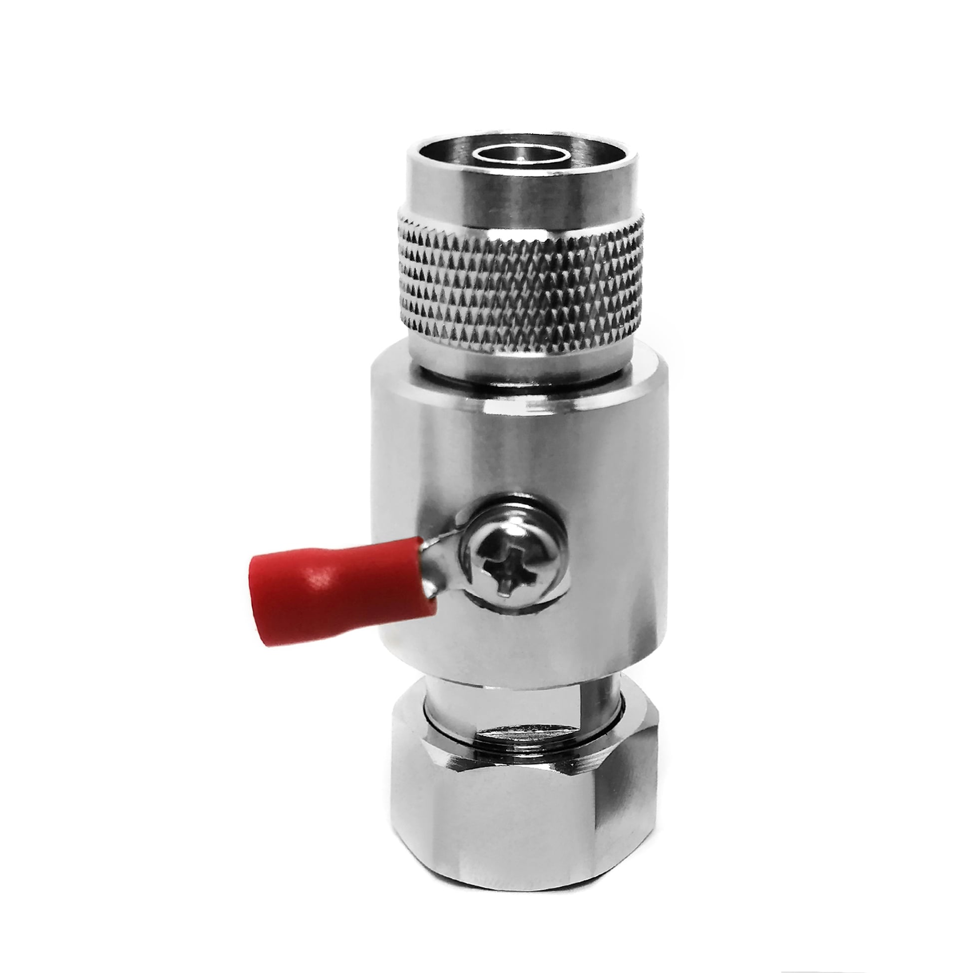
This 4.3-10 Male to N Male lightning arrester is a GDT based RF surge protector designed for DC - 3 GHz operation. It sits in the transmission line between the antenna and the radio equipment, diverting lightning-induced transients to ground before they reach the sensitive front end. The 50 ohm design holds insertion loss at 0.2 dB with a VSWR of 1.25 or better across the passband.
Request a Quote | Download Datasheet | Ask an Engineer
Product Overview
The 4.3-10 Male to N Male lightning arrester is an inline RF surge-protection device for 50 ohm coaxial lines from DC to 3 GHz. It is used at antenna feeders, radio entries, and other cable runs where lightning-induced or switching transients could reach RF equipment. A replaceable 90 V gas discharge tube provides the protective element. It remains at high impedance during normal service, allowing the RF path to operate with a stated insertion loss of 0.2 dB; during a surge, it ionizes and routes transient energy toward ground.
The 4.3-10 Male to N Male lightning arrester combines 4.3-10 male and N male interfaces in one device, supporting N-to-4.3-10 interconnects without an extra adapter. Its GDT structure is suited to low-capacitance, low-loss RF paths, and the tube can be serviced after a major event without replacing the entire arrester.
Protection Mechanism and Construction
The 4.3-10 interface is especially relevant where compact, high-density radio connections are used, while the N interface supports common RF feeder and equipment connections.
Reference Technical Specifications
The following reference values describe the stated configuration of this 4.3-10 Male to N Male lightning arrester. Confirm the final production configuration before specifying the device for a particular project or installation.
| Parameter | Specification | Notes |
|---|---|---|
| Connector Interface | 4.3-10 Male to N Male | Standard RF connector |
| Mounting Style | Inline | Body configuration |
| Impedance | 50 ohm | System impedance |
| Frequency Range | DC - 3 GHz | Passband |
| Insertion Loss | 0.2 dB | Across passband |
| VSWR | 1.25 | Maximum |
| Power Handling | 220 W | CW, reference |
| Discharge Element | 90 V | Gas discharge tube |
| Surge Current | 10 kA (8/20 us) | 8/20 us waveform |
| Grounding | Ring terminal | M4 lug, ground wire |
| Body Material | Machined brass | Corrosion-resistant plating |
| Weight | 135.1 g | Approximate |
| Typical Application | N to 4.3-10 interconnect, hybrid sites | Primary use case |
These values are provided as reference information for this protection family and should be verified against the final production configuration and the requirements of the RF system.
Engineering Comparison
Applications
Installation and Grounding Notes
OEM and B2B Support
FAQ
Q: When should the gas discharge tube be replaced?
A: The 90 V tube is stated for a 10 kA 8/20 us surge waveform. Following a major surge event, inspect and test the device according to the maintenance procedure used for the installation. If the tube does not meet the required hold-off or leakage condition, replace the serviceable element before returning the line to operation.
Q: Will the 4.3-10 Male to N Male lightning arrester affect a DC to 3 GHz RF signal?
A: The reference configuration lists 0.2 dB insertion loss and a maximum VSWR of 1.25 across the stated passband. Confirm the final device data against the specific frequency plan, connector condition, and system requirements before deployment.
Q: Can this arrester be used indoors?
A: Yes. The 4.3-10 Male to N Male lightning arrester may be used at an equipment-side cable entry or another point in the RF path where a suitable earth connection is available. Installation location and grounding should follow the overall protection layout for the site.