 EN
EN

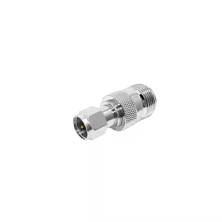
In high-frequency transmission systems, an adaptor rf is an active electrical transition rather than a simple hardware coupler. Whether linking bench instruments, connecting antenna distribution feeders, or adapting micro-miniature printed circuit boards to external chassis walls, coaxial transitions alter the electromagnetic field distribution of the transmission line. A poorly specified adapter introduces step discontinuities, capacitance fringing, and phase jitter, degrading system performance long before hardware reaches physical fatigue.
Engineering procurement requires evaluating physical interface geometries, dielectric properties, power handling, and RF vector reflection parameters across the operational band. Treating an interface adapter as a passive fitting invites unbudgeted link loss, impedance mismatch, and field failures.
Transmission Line Transitions and VSWR Dynamics
Every coaxial interface establishes a specific ratio between the outer conductor inner diameter and the center conductor outer diameter. This ratio, combined with the relative permittivity of the supporting dielectric, fixes the characteristic impedance. When an adaptor rf links disparate connector architectures, step discontinuities occur at the junction plane.
These mechanical steps generate localized shunt capacitance and series inductance. If these reactive components are left uncompensated, reflections elevate the Voltage Standing Wave Ratio (VSWR), generating signal attenuation and phase distortion. In high-power transmitter chains, elevated VSWR increases localized heating inside the adapter body, accelerating dielectric breakdown. Maintaining low return loss across microwave spectrums requires precise internal step compensation to cancel out fringing capacitance.
Intra-Series Coupling and Ground Continuity
Intra-series transitions provide inline connections between identical connector interfaces without introducing step geometry changes. However, mechanical execution dictates high-frequency electrical performance.
A bnc to bnc adapter serves as a prime example across test instrumentation, video distribution racks, and legacy communication links. Standard commercial barrel fittings often introduce contact resistance and ground loop noise through loose outer ground springs. High-performance barrel transitions utilize precision beryllium copper spring contacts with uniform gold plating to maintain ground shield continuity.
-
Maintaining uniform 50 Ω or 75 Ω line impedance across the internal barrel core prevents return loss degradation.
-
Hermetic and bulkhead configurations provide physical chassis isolation while sustaining environmental ingress protection.
-
Heavy-duty bayonet slots machined with tight mechanical clearances eliminate signal flutter under equipment vibration.
-
Dielectric materials such as virgin PTFE preserve low dielectric loss and high insulation resistance past 3 GHz.
When integrating a bnc to bnc adapter into calibration chains or broadcast monitoring setups, verifying insertion loss and return loss specifications prevents hidden measurement errors.
Micro-Coaxial Board Transitions and Mechanical Limits
Modern embedded RF modules, cellular IoT modems, and Wi-Fi transceivers rely on ultra-miniature board-mounted receptacles to minimize PCB space. Converting these delicate board nodes to panel-mounted interfaces requires a specialized ufl to sma adapter jumper assembly.
The primary vulnerability of miniature board connections is mechanical fragility rather than electrical loss. A micro-coaxial connector like the U.FL is mechanically rated for roughly 30 mating cycles before contact retention spring tension drops significantly. Direct axial pulls or side-loading from stiff external coaxial cables can shear the surface-mount solder pads off the circuit board.
Deploying a pre-assembled ufl to sma adapter pigtail provides essential mechanical decoupling. The flexible miniature coax absorbs structural shock, vibration, and panel flexing, isolating the delicate SMT receptacle.
Parameter
Standard Board Connection
External Panel Interface
Interface Family
U.FL / I-PEX MHF
SMA Female Bulkhead
Mechanical Coupling
Push-on snap engagement
Threaded 1/4-36 UNS coupling
Mating Cycle Endurance
Typically 30 cycles maximum
500 cycles minimum
Typical Cable Compatibility
0.81 mm, 1.13 mm, 1.37 mm micro-coax
RG-316, RG-178, or semi-rigid stock
Operational Frequency
DC to 6 GHz
DC to 18 GHz
Primary Failure Mode
PCB solder pad lift from cable torque
Center pin recess or thread galling
| Parameter | Standard Board Connection | External Panel Interface |
|---|---|---|
| Interface Family | U.FL / I-PEX MHF | SMA Female Bulkhead |
| Mechanical Coupling | Push-on snap engagement | Threaded 1/4-36 UNS coupling |
| Mating Cycle Endurance | Typically 30 cycles maximum | 500 cycles minimum |
| Typical Cable Compatibility | 0.81 mm, 1.13 mm, 1.37 mm micro-coax | RG-316, RG-178, or semi-rigid stock |
| Operational Frequency | DC to 6 GHz | DC to 18 GHz |
| Primary Failure Mode | PCB solder pad lift from cable torque | Center pin recess or thread galling |
Selecting an optimized ufl to sma adapter requires specifying exact pigtail lengths, internal shielding coverage, and O-ring bulkhead sealing to prevent RF leakage and environmental ingress through enclosure walls.
Impedance Mismatches in Commercial Coaxial Interfaces
Broadband distribution networks, satellite receivers, and commercial audiovisual systems frequently encounter a type f adapter during system integration. Operating at a 75 Ω characteristic impedance, the F-type interface utilizes an inexpensive 3/8-32 threaded coupling, often employing the solid copper-clad center conductor of the coaxial cable as the mating contact pin.
Mating a 75 Ω type f adapter directly into a 50 Ω RF network introduces an immediate impedance mismatch. The resulting reflection coefficient (Γ=0.20) produces an intrinsic VSWR of 1.5:1, reflecting roughly 4% of total incident signal power. In precision laboratory testing or digital communication transceivers, this discontinuity creates significant pulse distortion, inter-symbol interference, and high bit-error rates.
-
Verify system impedance before mating threaded coaxial hardware; physical thread compatibility does not guarantee electrical matching.
-
Deploy calibrated 50 Ω to 75 Ω impedance matching pads or broadband minimum-loss transformers when joining F-type infrastructure with 50 Ω instruments.
-
Avoid forcing large F-type center conductors into precision 50 Ω receptacles to protect internal spring contact fingers from permanent deformation.
-
Ensure that any commercial type f adapter utilized in video feeds provides solid internal shielding to block ambient electromagnetic interference.
Adaptor Type
Target System Impedance
Standard Frequency Range
Nominal Return Loss
Primary Use Case
Precision Intra-Series
50 Ω
DC to 18 GHz
> 26 dB (to 6 GHz)
Lab test benches, vector calibration
Standard Inter-Series
50 Ω
DC to 11 GHz
> 20 dB (to 4 GHz)
Field radio links, antenna feeds
BNC Barrel Unit
50 Ω or 75 Ω
DC to 3 GHz / 12 GHz
> 20 dB (to 3 GHz)
Patch panel extension, video links
Board Pigtail Unit
50 Ω
DC to 6 GHz
> 18 dB (to 3 GHz)
Embedded IoT, wireless module routing
Commercial F-Series
75 Ω
DC to 1 GHz / 3 GHz
> 15 dB (to 1 GHz)
Satellite feeds, CATV headend drops
| Adaptor Type | Target System Impedance | Standard Frequency Range | Nominal Return Loss | Primary Use Case |
|---|---|---|---|---|
| Precision Intra-Series | 50 Ω | DC to 18 GHz | > 26 dB (to 6 GHz) | Lab test benches, vector calibration |
| Standard Inter-Series | 50 Ω | DC to 11 GHz | > 20 dB (to 4 GHz) | Field radio links, antenna feeds |
| BNC Barrel Unit | 50 Ω or 75 Ω | DC to 3 GHz / 12 GHz | > 20 dB (to 3 GHz) | Patch panel extension, video links |
| Board Pigtail Unit | 50 Ω | DC to 6 GHz | > 18 dB (to 3 GHz) | Embedded IoT, wireless module routing |
| Commercial F-Series | 75 Ω | DC to 1 GHz / 3 GHz | > 15 dB (to 1 GHz) | Satellite feeds, CATV headend drops |
Quality Standards and Factory Verification Protocols
Industrial procurement specifications demand rigorous manufacturing controls to guarantee that every adaptor rf delivers repeatable electrical performance across extended operational cycles.
-
Dimensional Tolerances: Interface dimensions must strictly comply with IEC 61169 and MIL-STD-348 standards, verified using non-contact optical profile projectors.
-
Contact Metallurgy: Center contact pins require machined beryllium copper or phosphor bronze with hard gold plating over a nickel underplate to withstand 500 mating cycles without flaking.
-
Dielectric Consistency: High-grade virgin PTFE or polyetherimide dielectrics must exhibit uniform density to prevent dielectric constant variations.
-
Environmental Testing: Plating layers must pass 48-hour or 96-hour neutral salt-spray tests according to MIL-STD-202 Method 101 to verify corrosion resistance in marine or outdoor settings.
-
S-Parameter Verification: Factory sweep tests on Vector Network Analyzers (VNA) must validate insertion loss, return loss, and VSWR limits across the full rated frequency band.
Manufacturing Precision and Supply Chain Solutions with Worldpeak
High-reliability RF applications depend on consistent mechanical tolerances and verified electromagnetic parameters across production volumes. As a specialized RF hardware manufacturer and global exporter, Worldpeak provides end-to-end engineering, custom fabrication, and OEM/ODM supply chain services for mission-critical connectivity. High-precision CNC Swiss turning centers maintain machining tolerances down to ±0.005 mm, ensuring that every adaptor rf delivers seamless mechanical mating and minimal reflection.
The manufacturing infrastructure at Worldpeak encompasses complete testing workflows, including Vector Network Analyzer sweep testing up to 18 GHz, contact retention force gauging, and X-ray fluorescence plating thickness analysis. From heavy-duty outdoor transitions and laboratory-grade bnc to bnc adapter components to high-density ufl to sma adapter cable harnesses, Worldpeak supports global industrial clients with flexible minimum order quantities, rapid sample prototyping, and scalable manufacturing. Engineering teams and procurement specialists can partner directly with Worldpeak to resolve complex interface mismatches with field-proven hardware.





