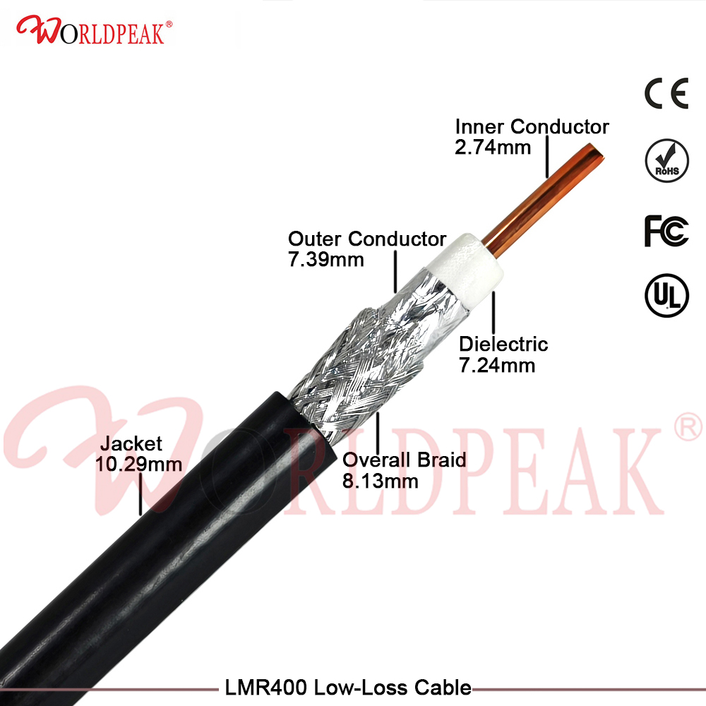
A reliable LMR-400 crimper tool is the core guarantee for stable connection of LMR-400 low-loss coaxial cables in 5G base stations, maritime communication and IoT network systems. Improper tool selection or non-standard crimping operation will directly cause increased signal attenuation, reduced shielding performance and even loose connector falling off, seriously affecting the long-distance transmission stability of RF signals. As a professional coaxial cable crimper manufacturer and RF solution supplier, our factory has 20+ years of production experience and strict quality inspection standards. This guide focuses on the professional selection logic and standardized installation steps ofLMR-400 installation guide, helping B2B buyers and engineering practitioners avoid common crimping failures and optimize RF connector crimping efficiency and yield.
Key Parameters for Selecting LMR-400 Crimper Tool
The selection of LMR-400 crimper tool cannot rely on general-purpose tools. LMR-400 low-loss coaxial cable has a specific outer diameter, shielding structure and dielectric thickness, which puts forward strict matching requirements for the crimping die size, pressure uniformity and structural design of the coaxial cable crimper. Matching parameters directly determine the crimping tightness, shielding effectiveness and tensile resistance of the finished product, and are the primary standard for procurement and selection.
|
Selection Parameter
|
Standard Requirement for LMR-400
|
Unqualified Tool Performance
|
Engineering Impact
|
|
Crimping Die Size
|
10.90mm standard cavity, dedicated for LMR-400 cable ferrule
|
Universal die with inaccurate size, large tolerance
|
Uneven crimping, poor fitting gap
|
|
Tool Material
|
Hardened carbon steel with anti-corrosion black oxide finish
|
Ordinary steel, easy to deform and rust
|
Inaccurate pressure, short service life
|
|
Ratchet Structure
|
Full-cycle self-locking ratchet, automatic release after standard crimping
|
No ratchet or incomplete locking function
|
Insufficient pressure, loose crimped joints
|
|
Shielding Matching
|
Adapt to LMR-400 aluminum foil + tinned copper braid shielding
|
Only suitable for single-layer braided shielding cable
|
Damaged shielding layer, reduced anti-interference performance
|
Professional RF connector crimping tools must fully match the structural characteristics of LMR-400 cables. Different from ordinary RG series coaxial cables, LMR-400 adopts physical foam dielectric and composite shielding structure. Only the special LMR-400 crimper tool can avoid damaging the aluminum foil shielding layer during crimping, ensuring that the shielding effectiveness of the cable remains above 90dB and low attenuation transmission performance is not compromised.
Standard Installation Steps of LMR-400 Crimping (Professional Operation Guide)
Scientific installation steps are the key to qualified crimping results, which is also the core content of our standardized LMR-400 installation guide. Combining the factory's long-term engineering practice and pre-shipment inspection standards, the standardized coaxial cable crimper operation process is summarized below to eliminate operational errors.
First, complete cable stripping pretreatment. According to the interface specifications of LMR-400 RF connectors, strip the outer jacket, foam dielectric and inner conductor insulation layer in sections. It is necessary to avoid scratching the inner conductor and damaging the aluminum foil shielding layer, which is the premise of high-quality RF connector crimping. Second, insert the processed LMR-400 cable into the matching RF connector, ensure the inner conductor is fully fitted and the shielding braid is evenly covered on the connector ferrule.
Third, position the LMR-400 crimper tool accurately. Align the standard die of the crimper with the connector ferrule, keep the tool vertical and avoid offset clamping. Squeeze the tool handle steadily until the ratchet structure automatically releases, which means the crimping pressure reaches the standard value. Do not manually force the handle to open to prevent insufficient crimping or structural deformation.
Finally, conduct post-crimping quality inspection. Check whether the crimped ferrule is evenly compressed without bulging, cracking or deformation. Test the tensile firmness of the connector, and conduct network analyzer testing for batch products to verify that the signal attenuation and impedance parameters meet 50Ω standard requirements. All products of our factory pass CE, RoHS and FCC certification, and each batch of crimping supporting accessories undergoes strict factory testing to ensure engineering applicability.
Common Crimping Failures and Avoidance Tips
In actual engineering applications, most LMR-400 signal instability problems are caused by non-standard RF connector crimping rather than cable quality problems. Using mismatched universal coaxial cable crimper is the primary cause of failure. For example, too small die size will crush the cable dielectric layer, resulting in increased signal loss; too large die size will cause loose crimping and poor contact.
In addition, incomplete cable stripping and uneven shielding layer distribution will lead to local signal leakage and reduced anti-interference ability. Following the exclusive LMR-400 installation guide and supporting special LMR-400 crimper tool can effectively solve the above problems, improve the one-time pass rate of crimping, and reduce after-sales maintenance costs for engineering projects.
Conclusion
The performance of LMR-400 crimper tool directly determines the transmission quality and service life of LMR-400 low-loss coaxial cable systems. Selecting a professional and matching coaxial cable crimper and implementing standardized operation in accordance with the LMR-400 installation guide are essential links to ensure efficient and stable RF connector crimping. As a professional RF cable and accessory manufacturer, we support OEM/ODM customization, batch wholesale and technical guidance services, providing one-stop high-quality solutions for global communication engineering buyers.
 EN
EN