 EN
EN

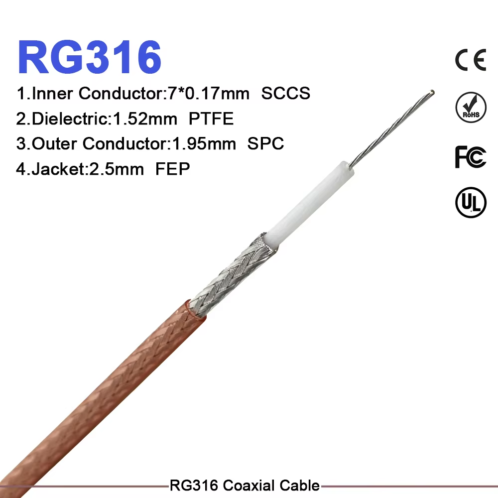
Selecting an rf cable is a core system architecture decision rather than a simple component sourcing task. Operating between RF signal sources, antennas, radios, filters, and measurement instruments, a cable assembly directly dictates total link attenuation, shielding isolation, and phase stability. For B2B procurement teams and system engineers, establishing clear electrical tolerances and physical routing parameters guarantees long-term signal stability across complex communication networks.
Using a cable solely because it physically mates with existing interfaces frequently introduces impedance mismatches, elevated Insertion Loss (IL), and premature mechanical failure. Evaluating high-frequency performance metrics before finalizing custom manufacturing orders ensures predictable operation under challenging real-world conditions.
Fundamental Electrical Metrics of High-Frequency Signal Lines
The primary functional objective of an rf cable is carrying electromagnetic energy with controlled characteristic impedance and minimal signal leakage. In wireless infrastructure, cellular base stations, military radar, and lab testing environments, a 50 ohm rf cable serves as the standard transmission standard. This 50-ohm baseline balances power handling capacity with low signal attenuation.
Deploying unmatched components—such as substituting a 75-ohm cable into a 50-ohm communication path—creates an impedance boundary. This mismatch reflects signal energy back toward the transmitter source, elevating the Voltage Standing Wave Ratio (VSWR), distorting digital modulation schemes, and generating thermal stress within active power amplifiers.
Key Performance Metrics for B2B Component Evaluation
Attenuation and Link Margin Preservation
Every rf cable exhibits dielectric and conductor losses that increase with signal frequency and overall physical length. For short internal enclosure jumpers, physical flexibility takes priority over minimal loss variations. Conversely, for long outdoor rf antenna cable runs or weak receiver paths, choosing low-loss dielectrics (such as expanded PTFE foam) preserves critical link budget headroom.
When evaluating supplier datasheets, engineering teams must review swept attenuation figures at specific operating frequencies rather than accepting generic "low-loss" commercial labels.
Shielding Effectiveness and Interference Containment
Outer conductor construction determines how effectively an rf cable blocks external electromagnetic interference (EMI) while containing internal signal emissions. Heavy industrial environments—packed with switching power supplies, variable frequency drives, and dense transmitter arrays—demand high shielding isolation.
-
Single Braid Shielding: Offers baseline mechanical flexibility; typical shielding effectiveness sits around -40 dB to -50 dB.
-
Double Braid / Foil-Braid Combinations: Provides enhanced shielding effectiveness reaching -80 dB to -90 dB, ideal for dense cabinet wiring.
-
Solid / Corrugated Metallic Outer Conductors: Provides superior shielding performance exceeding -100 dB, isolating critical outdoor feeder paths.
Mechanical Integrity and Cable Routing Dynamics
Mechanical strain directly impacts electrical performance. Bending an rf cable beyond its specified minimum bend radius compresses the internal dielectric core, shifting the center conductor off-center. This physical deformation alters localized characteristic impedance, triggering standing wave spikes. Defining connector clocking angles and strain-relief boot placements during the initial drafting phase prevents physical stress at the cable-to-connector junction.
Engineering Analysis of Standard RF Cable Types
Differentiating between various rf cable types allows engineers to select the optimal mechanical build for specific operational environments.
| Cable Category | Core Structural Characteristics | Ideal Application Scenarios | Engineering Trade-offs |
| Flexible Coaxial Lines | Stranded/solid core with braided shielding | Moving enclosures, service jumpers, and test leads | Higher attenuation per meter at microwave frequencies |
| Semi-Rigid Coax | Solid copper or aluminum outer tubing | Formed internal chassis routes and phase-matched paths | Requires precision bending tools; impossible to re-bend in field |
| Hand-Formable Coax | Tin-soaked braided outer conductor | Custom internal prototype jumpers and tight chassis paths | Retains shape after bending; limited flex life |
| Corrugated Feeder Lines | Helical or annular corrugated outer conductor | Outdoor base station feeders and long rf antenna cable runs | Large outer diameter; requires specialized mounting hardware |
Reviewing these rf cable types against mechanical constraints ensures that high-flexibility jumpers are assigned to dynamic service loops, while rigid corrugated feeders are designated for long outdoor tower runs.
Custom Specification Checklist for Technical Procurement
To streamline clarification cycles with manufacturing partners, B2B procurement packages for custom assemblies should explicitly state:
-
Nominal system impedance (confirming a 50 ohm rf cable or 75-ohm architecture).
-
Operating frequency band and maximum permissible insertion loss budget across the total length.
-
Cable outer diameter constraints and shielding effectiveness targets (in dB).
-
Connector series, gender, straight or right-angle orientation, and body plating specifications.
-
Exact finished assembly length, measured interface-to-interface or reference-plane to reference-plane.
-
Environmental compliance mandates, including UV resistance, flame retardancy (LSZH), or IP67/IP68 ingress protection.
-
Quality acceptance testing standards, such as 100% vector network analyzer (VNA) swept VSWR and insertion loss certification.
Specialized Integration Scenarios
Different industrial deployments alter component selection priorities:
-
Telecommunications and Distributed Antenna Systems (DAS): Requires low Passive Intermodulation (PIM) ratings, weather-sealed outer jackets, and long-term impedance stability.
-
Industrial Automation & Robotics: Prioritizes high flex-life cycles, continuous vibration tolerance, and robust oil/chemical resistance.
-
Test Laboratories & Calibration Facilities: Focuses on phase stability across thermal cycles, low VSWR, and durable connector interfaces.
-
Aero-Defense and Mobile Networks: Emphasizes lightweight materials, space-saving footprints, and broad operating temperature ranges.
Precision Manufacturing and Global Supply Infrastructure
Delivering high-reliability interconnects for modern RF systems requires tight manufacturing tolerances, automated processing equipment, and rigorous RF sweep testing. Worldpeak is a premier manufacturer of high-precision RF connectors, adapters, and custom cable assemblies engineered for telecommunications, test and measurement, and industrial infrastructure.
Utilizing automated stripping machinery, calibrated crimping tools, and advanced vector network analyzers (VNAs), Worldpeak produces high-performance rf cable assemblies tailored to exacting OEM specifications. Through strict raw material selection, comprehensive lot traceability, and flexible B2B manufacturing workflows, Worldpeak supports global customers with scalable, highly dependable interconnect solutions built for long-term service.





