 EN
EN

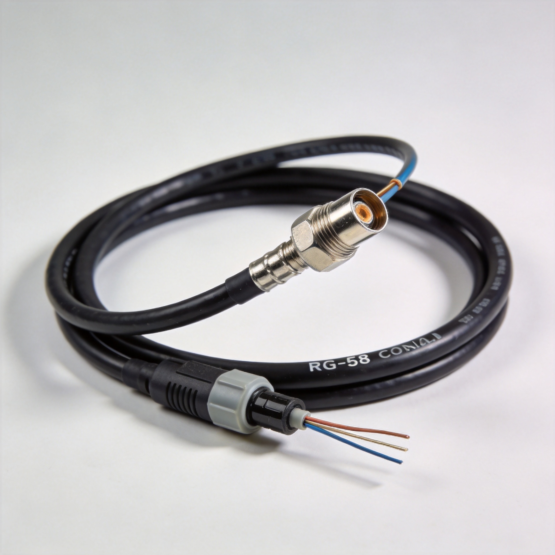
Selecting the right rg58 coax is less about buying a familiar cable designation and more about preserving systemic electrical integrity across the entire transmission path. In radio communications, test laboratories, industrial telemetry, and wireless infrastructure, matching system impedance takes top priority. Evaluating frequency-dependent attenuation, mechanical bend limits, shield coverage, and connector compatibility prevents a frequent field mistake: installing a physically flexible line that undermines system performance.
As a staple in 50-ohm transmission systems, rg58 coax serves low-power RF links, antenna jumpers, instrument leads, and internal equipment harnesses. However, exact attenuation curves, continuous power handling, temperature limits, and shielding effectiveness vary by manufacturer construction. Reviewing complete engineering datasheets guarantees that a chosen rg58 coax cable meets actual system loss budgets.
Characteristic Impedance in 50-Ohm RF Systems
The primary functional metric of rg58 coax is its 50-ohm characteristic impedance. In a balanced 50-ohm signal chain, the transmitter source, interconnect cable, mating adapters, and antenna load share identical impedance values to minimize standing waves. Selecting a genuine 50-ohm rg58 coax cable reduces Voltage Standing Wave Ratio (VSWR), preventing power reflection that can distort signals or overload sensitive power amplifiers.
Characteristic impedance is determined strictly by the physical geometry between the center conductor, the dielectric material, and the outer shielding braid—it is completely independent of direct-current resistance or overall line length. Extending the physical length of a cable run does not alter its 50-ohm characteristic impedance. However, line length directly increases total high-frequency attenuation. Evaluating insertion loss across operating frequencies ensures that long interconnect runs remain within the link margin budget.
Comparative Performance Metrics Across Common Coaxial Families
Coaxial lines are engineered around specific impedance targets and structural profiles. Substituting one family for another without verifying system parameters often compromises signal clarity.
| Cable Family | Nominal Impedance | Primary Selection Criteria & Target Applications |
| RG58 | 50 Ω | Flexible 50-ohm RF jumpers, radio antenna feeds, and mobile test leads |
| RG6 | 75 Ω | Broadband CATV, satellite TV distribution, and 75-ohm baseband video |
| RG174 | 50 Ω | Ultra-compact, space-restricted, low-power internal board interconnects |
| RG213 | 50 Ω | Heavy-duty, low-loss main antenna feeders for high-power installations |
| RG316 | 50 Ω | High-temperature, fluoropolymer-insulated military and aerospace leads |
| RG8X | 50 Ω | Low-loss mid-size compromise between thin RG58 and bulky RG213 runs |
A dedicated rg 6 coax cable belongs to a completely different design path. Engineered specifically for 75-ohm broadband networks, deploying an rg 6 coax cable inside a 50-ohm radio circuit introduces immediate impedance mismatch, raising VSWR and causing signal distortion. When high flexibility and manageable routing take priority in a 50-ohm circuit, rg58 coax remains the industry standard. For slightly longer antenna runs where lower attenuation is needed without accepting the bulk of RG213, an rg 8x coax cable serves as an effective intermediate option.
Specifying Precision RF Cable Assemblies
Requesting a turnkey rg58 coax cable assembly requires precise technical parameter callouts. Simply specifying a nominal cable type frequently leads to batch variations and unpredictable RF performance.
To establish a repeatable bill of materials, engineering specifications must detail the following core elements:
-
Conductor and Dielectric Core: Solid or stranded center conductor options based on flexing requirements, paired with solid polyethylene or foam dielectric cores.
-
Shielding Construction: Tinned copper braiding percentage, or foil-plus-braid dual shielding for enhanced electromagnetic interference suppression.
-
Exact Mechanical Length: Stating mechanical length tolerances or phase-matched electrical length requirements.
-
Termination Specifications: Specifying exact connector series, gender, pin plating thickness, straight or right-angle geometry, and crimp/solder attachment methods.
-
Outer Sheath Material: Indoor PVC jackets, or UV-resistant, flame-retardant, Low-Smoke Zero-Halogen (LSZH) materials for outdoor or industrial environments.
-
Quality Acceptance Testing: Mandatory VSWR testing, sweep testing across active operating bands, and high-potential dielectric withstand checks.
Field Routing, Strain Relief, and Termination Practices
Achieving long-term reliability with rg58 coax requires disciplined handling during field installation. Over-torquing connectors, exceeding minimum bend radii, or pinching outer jackets crushes the internal dielectric core. This physical deformation alters center-to-braid spacing, creating localized impedance spikes that degrade return loss.
When routing an rg58 coax cable inside electrical cabinets, maintain smooth service loops and isolate cable runs from sharp metal edges. Outdoor installations require immediate weatherproof sealing over every mated interface to prevent moisture ingress into the braid. During connector crimping, utilizing precision stripping tools and calibrated die sets prevents nicking internal conductor strands, ensuring uniform mechanical retention and stable signal transmission.
Essential Engineering Verification Checklist
Before releasing a coaxial line into active service, engineering teams should execute a systematic evaluation:
-
Confirm system architecture requirements (strictly 50-ohm vs 75-ohm lines).
-
Verify that signal attenuation over the total cable length fits the transmitter link budget.
-
Compare physical constraints between rg58 coax, RG174, RG316, and rg 8x coax cable options.
-
Ensure no 75-ohm lines, such as an rg 6 coax cable, are erroneously integrated into 50-ohm RF paths.
-
Validate connector pin plating, crimp barrel dimensions, and heat-shrink strain relief quality.
-
Request factory swept-frequency test data for return loss and insertion loss on high-reliability runs.
Precision Manufacturing and Custom Interconnect Infrastructure
Maintaining consistent high-frequency transmission across commercial and industrial deployments requires stringent raw material selection, precise termination equipment, and automated quality control. Worldpeak specializes in manufacturing precision RF connectors, high-performance adapters, and custom cable assemblies engineered to strict international standards.
Equipped with automated stripping machinery, calibrated crimping stations, and advanced vector network analyzers (VNA), Worldpeak supplies fully swept, low-loss interconnect solutions tailored for global OEMs, telecom operators, and industrial system integrators. By aligning precise cable geometry with disciplined manufacturing controls, Worldpeak ensures every custom cable assembly delivers dependable performance across demanding operating environments.





