EN
EN

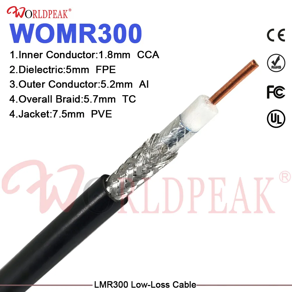
Selecting low-loss feeder lines is often the first step when an RF signal path requires reliable power transfer across extended runs. It is rarely the final step. Final installed attenuation depends heavily on total physical length, connector choice, mechanical strain relief, weatherized sealing, and pre-deployment testing. A custom lmr400 cable assembly transforms these variable field factors into a controlled electrical component, removing unpredictable guesswork from critical RF infrastructure.
Total system insertion loss is built from several combined factors: dielectric loss within the foam polyethylene geometry, skin resistance across the inner and outer conductors, connector impedance mismatches, adapter interface accumulation, and unnecessary cable over-length.
For telecommunications, remote security monitoring, industrial automation, laboratory test benches, and outdoor antenna installations, overall transmission efficiency is more than a simple datasheet specification. True system reliability depends on whether the deployed cabling matches equipment interfaces perfectly without introducing mismatch losses or mechanical stress. That is where a factory-built lmr400 low loss coaxial cable assembly delivers measurable operating benefits over field-crimped alternatives.
RF Feeder Performance as an Integrated System Goal
Data sheets for 50-ohm flexible low-loss coaxial lines often highlight baseline attenuation figures, such as approximately 4.25 dB per 100 feet at 1 GHz under ideal lab conditions. While useful for preliminary link budget calculations, published cable attenuation represents a baseline, not a guaranteed field result. Frequency scaling, conductor metallurgy, ambient thermal shifts, and physical routing continuously alter actual signal integrity.
When comparing a field-crimped bulk feeder against a factory-prepared custom assembly, the differences become obvious:
-
Cable Length: Loose bulk coils frequently leave arbitrary extra length, causing unnecessary attenuation. Factory custom runs are cut to exact measured dimensions.
-
Adapter Usage: Field runs often rely on improvised adapters that introduce reflection loss. Custom assemblies build direct connector interfaces into the line.
-
Termination Quality: Manual hand crimps invite mechanical wear and impedance variations over time, whereas precision factory termination protects shielding integrity.
-
Quality Assurance: On-site hand checks provide limited visibility, while swept frequency verification before shipment guarantees low VSWR performance.
Bulk cable delivered on spools can exhibit excellent dielectric characteristics, yet underperform once deployed. Excessive line length, tight bend radii near connector collars, improper interface mating, and moisture intrusion quickly compromise link margins. Individual installation flaws combine to degrade systemic link budgets, making signal troubleshooting difficult when the nominal cable selection appears correct on paper.
How Custom Assembly Eliminates Avoidable Path Losses
Tailoring Cable Length to the Specific Physical Path
Excess physical length creates unnecessary signal loss. Incorporating a dedicated custom lmr400 cable assembly engineered to exact site dimensions preserves signal power by eliminating coiled slack.
Calculated service loops provide adequate clearance for maintenance without leaving meters of unused cable tied to towers or racks. On rooftop deployments and equipment enclosures, precise length specifications eliminate tight cable loops, preventing localized impedance changes caused by crushed dielectric layers.
Engineering Connector Interfaces Prior to Installation
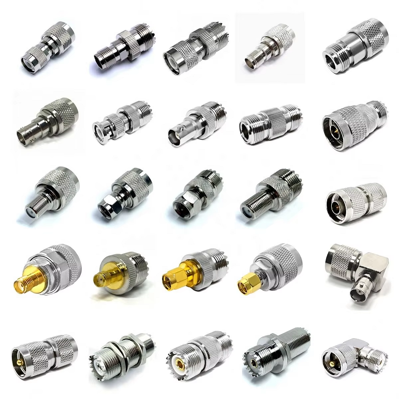
Antenna ports, surge protectors, radios, and test equipment often use diverse RF interface standards and gender configurations. Factory integration of exact connector types—such as N-Type, SMA, or TNC—eliminates the need for inline adapters.
Direct factory termination provides an optimal single-run path with low VSWR between the radio interface and antenna port. In contrast, an improvised field adapter stack creates cumulative reflection and insertion loss at every threaded transition.
While inline adapters resolve mechanical mating issues, each threaded transition adds insertion loss and potential impedance mismatches. Specifying direct connector terminations on the primary lmr400 low loss coaxial cable assembly minimizes return loss, protects weather-sealing integrity, and keeps overall rf signal loss reduction targets on track.
Standardizing Mechanical Strain Relief and Routing Radius
Flexible coaxial lines must be installed within safe mechanical bend limits. Solid center conductors and foamed polyethylene dielectrics can deform under severe bending, altering internal geometry and causing signal reflections.
Specifying custom assemblies allows engineers to select the best cable jacket for the environment—such as flame-retardant plenum jackets for indoors, direct-burial jackets, or ultra-flexible strands for moving equipment. Integrating factory-molded strain relief boots and targeted bend support protects delicate junction points, preventing mechanical fatigue over extended outdoor use.
| Parameter | Field-Terminated Run | Custom Factory Assembly |
| Length Accuracy | Variable / Coiled Slack | Exact Measured Route |
| Interface Adapters | Frequently Required | Zero (Direct Interface) |
| Electrical Verification | Handheld Field Checks | Swept VSWR / Loss Data |
| Water & Dust Ingress | Tape/Heat-Shrink Dependent | Molded IP67 Boots |
| Impedance Continuity | Hand-Crimped Variances | Precision Tooling |
Verifying Electrical Integrity Before Deployment
Building coaxial assemblies on-site requires specialized stripping tools, calibrated crimpers, and skilled field technicians. Even with proper equipment, achieving consistent RF performance across multiple site locations remains a challenge.
Factory-finished low loss feeder assemblies establish clear baseline quality control prior to shipment. Connectors, conductor termination, and overall physical dimensions are validated against strict manufacturing drawings.
Production lines equipped with vector network analyzers perform automated frequency sweeps, verifying insertion loss and Voltage Standing Wave Ratio (VSWR) limits before shipping. Providing verified test documentation ensures that installed cables meet system performance requirements right out of the box.
Recommended Field Practices for Low-Loss Coaxial Installations
-
Verify System Impedance & Operating Frequency: Confirm that all system ports maintain a 50-ohm characteristic impedance across the required operating frequency band.
-
Calculate Precise Physical Lengths: Plan physical cable paths to include necessary service loops while avoiding excessive coiled slack.
-
Define Direct Connector Interfaces: Identify equipment port types, genders, and thread styles early to specify direct connector terminations and eliminate adapter stacks.
-
Plan Correct Bend Radii and Support: Secure cables along structured tray networks, adhering to minimum bend radius rules to prevent conductor migration or dielectric deformation.
-
Apply Comprehensive Environmental Sealing: Use UV-stabilized jackets, weatherproof boots, or cold-shrink tubing to protect exterior connector interfaces from moisture ingress.
-
Validate Pre-Shipment Test Documentation: Review swept insertion loss and VSWR test reports prior to final field installation.
Operational Scenarios for Pre-Terminated Coaxial Lines
Factory-terminated low loss feeder assemblies are valuable in applications where signal margin is limited, installation space is restricted, or field rework is costly:
-
Remote Cellular and IoT Gateways: Minimizing feeder attenuation on tall antenna masts directly improves receive sensitivity and coverage area.
-
Industrial Automation & Supervisory Systems: Custom flexible routing ensures stable signal transmission near moving machinery without mechanical wear.
-
Distributed Antenna Systems (DAS): Pre-measured runs speed up indoor installation while keeping total link loss within strict system designs.
-
Laboratory & Microwave Test Stations: Verified phase stability and low return loss are essential for accurate, repeatable measurements.
Integrating Precision Assemblies into Engineering Workflows
Customized coaxial cable configurations shift cable management from an unpredictable field task to a controlled design specification. Specifying pre-cut lengths, direct connector interfaces, and protective jacketing ensures predictable electrical performance, clean installations, and long-term operating reliability.
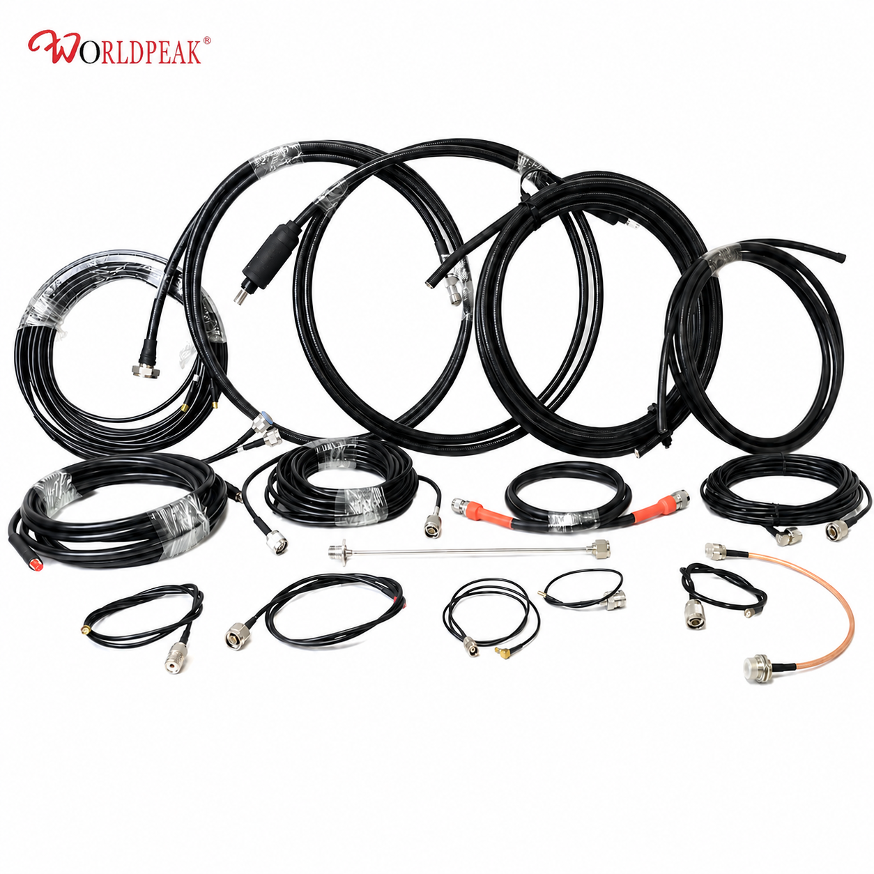
To simplify installation workflows, WORLDPEAK provides precision-engineered RF connectivity products, including custom coaxial assemblies and high-frequency connectors. Built with automated stripping equipment and verified through VNA sweep testing, these factory-assembled solutions deliver consistent impedance matching and low return loss for critical wireless networks worldwide.