 EN
EN

BNC Cable Connector: Termination Guide for RF Systems
I've designed RF signal chains for video surveillance backbone infrastructure and precision laboratory instrument setups, and the BNC cable connector consistently shows up at both ends of that spectrum. It is a mature interface, and yet selecting the right impedance, physical variant, and termination method for a specific deployment is something that trips up experienced engineers more often than you'd expect. This guide provides a practical, application-oriented walkthrough of the key decisions.
Application Areas: Where This Interface Is Used and Why
The BNC cable connector's bayonet locking mechanism and compact form factor have made it the default interface across three distinct application domains. Understanding how each domain's requirements differ is the starting point for correct selection of any bnc cable connector.
Video surveillance and CCTV systems rely on this interface to carry composite and HD-SDI signals at relatively low frequencies. The 75Ω characteristic impedance dominates here because it matches broadcast and video coaxial cable. Using a 50Ω bnc cable connector on a 75Ω video system introduces reflections that show up as elevated VSWR and signal degradation in HD-SDI infrastructure.
Test and measurement equipment—oscilloscopes, signal generators, spectrum analyzers, vector network analyzers—uses the 50Ω variant as standard. The interface is rated to 500 minimum mating cycles under MIL-STD-348 with insertion loss of no more than 0.2 dB at 3 GHz. Extended-range designs operate from DC through 12 GHz, covering most lab measurement needs below the SMA or N-type transition.
For radio communications and RF distribution frames, the 50Ω variant achieves VSWR of 1.3:1 maximum from DC to 4 GHz, keeping reflected power low enough to protect transmitter outputs. Power handling reaches approximately 316 W at 1 GHz at 25°C—adequate for most low-power RF applications.
I initially assumed that the same bnc cable connector selection approach applied equally to video distribution panels and RF test benches. The distinction became clear when a video infrastructure project specified 50Ω interfaces throughout: VSWR was elevated at every point in the system, tracing directly to the impedance mismatch. What worked on the RF bench actively created reflections on the video bus.
Standard, Right-Angle, and Panel-Mount Variants
Once the impedance decision is made, the physical variant determines which configuration fits the installation.
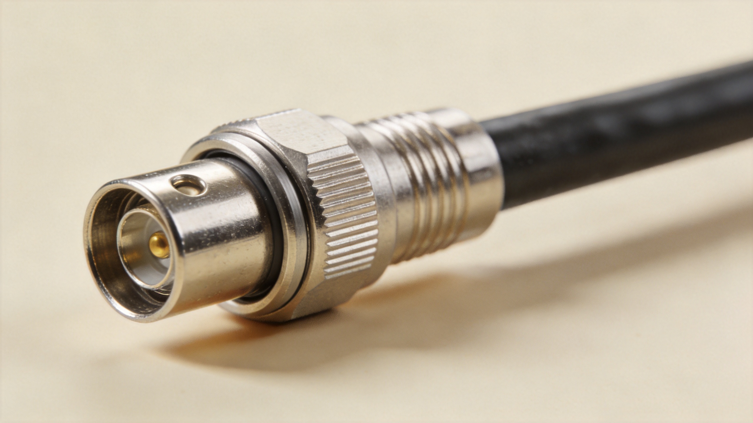
The straight BNC cable connector is the default when routing is unconstrained. It provides the most predictable impedance continuity through the body and the lowest mechanical stress on the cable during installation.
The right-angle variant suits installations where the assembly must exit a panel at 90 degrees. Right-angle configurations introduce a measurable VSWR increase versus straight variants, particularly near the upper end of the 4 GHz operating range. If your application stays below 4 GHz and physical clearance is the primary constraint, a right-angle bnc cable connector is practical; as frequency approaches the limit, the VSWR contribution from the angle transition should enter the link budget.
The panel-mount variant is used where a chassis wall must present a fixed interface to an external assembly. This configuration is common in rack-mounted equipment, test fixture chassis, and RF distribution panels. Verify panel thickness compatibility with the manufacturer's specification before ordering—this is a detail that is easy to overlook and difficult to fix after the chassis is drilled.
50Ω vs. 75Ω: Matching Impedance to the Application
The physical difference between 50Ω and 75Ω versions of this interface is subtle—primarily the center contact diameter and dielectric geometry—but the electrical consequence of mismatching them with the cable or equipment is not. Standard 50Ω models achieve VSWR of 1.3:1 maximum from DC through 4 GHz; the 75Ω version is rated to 1.5:1 over the same range. Using a 50Ω bnc cable connector on a 75Ω cable system introduces a reflection coefficient of roughly 0.2 at each mating interface—a ballpark estimate, not a number for a link budget without measurement, but it conveys the scale of the mismatch problem.
The pairing rule: 75Ω for video and broadcast assemblies; 50Ω for RF, test equipment, and radio applications. In mixed-impedance environments, a dedicated 50Ω-to-75Ω adapter at the transition point is preferable to specifying a hybrid that meets neither system's tolerance cleanly.
For applications requiring tight impedance control across the full operating range, the BNC-ULTRA100 Precision BNC Connector combines 50Ω characteristic impedance with ±0.02 mm contact tolerance and a stainless steel body, meeting MIL-STD-348—a practical choice for high-accuracy measurement or military-grade RF system deployments.
Crimp and Solder Termination: Cable Type Compatibility
Termination method determines the long-term reliability of the interface-to-cable junction. Both crimp and solder are used with this interface; the better choice depends on cable type, production volume, and installer skill.
Crimp termination dominates in volume production and field installation. It is faster than soldering and produces consistent results when the correct crimp tool and die set are used. The critical dependency is cable compatibility: crimp versions are manufactured to specific cable outer diameters, and using a crimp body dimensioned for RG-58 on an RG-174 cable results in an undersized crimp that fails under vibration or thermal cycling. For the rg174 bnc connector, which fits 0.100-inch outer diameter cable types including RG-174, RG-316, and LMR-100A, a dedicated crimp die sized for the smaller OD is essential. RG-58 and RG-8X require their own rg174 bnc connector and die specifications.
Solder termination offers flexibility in prototype or low-volume assembly where cable types vary and dedicated crimp tooling for each variant is uneconomical. The trade-off is skill sensitivity: inconsistent solder flow into the braid can create a rigid joint at the cable exit, leading to intermittent contact after repeated flexing. A well-executed solder joint is reliable; a marginal one is hard to identify visually and often fails only after deployment.
Pre-Terminated Assemblies and Cross-Interface Configurations
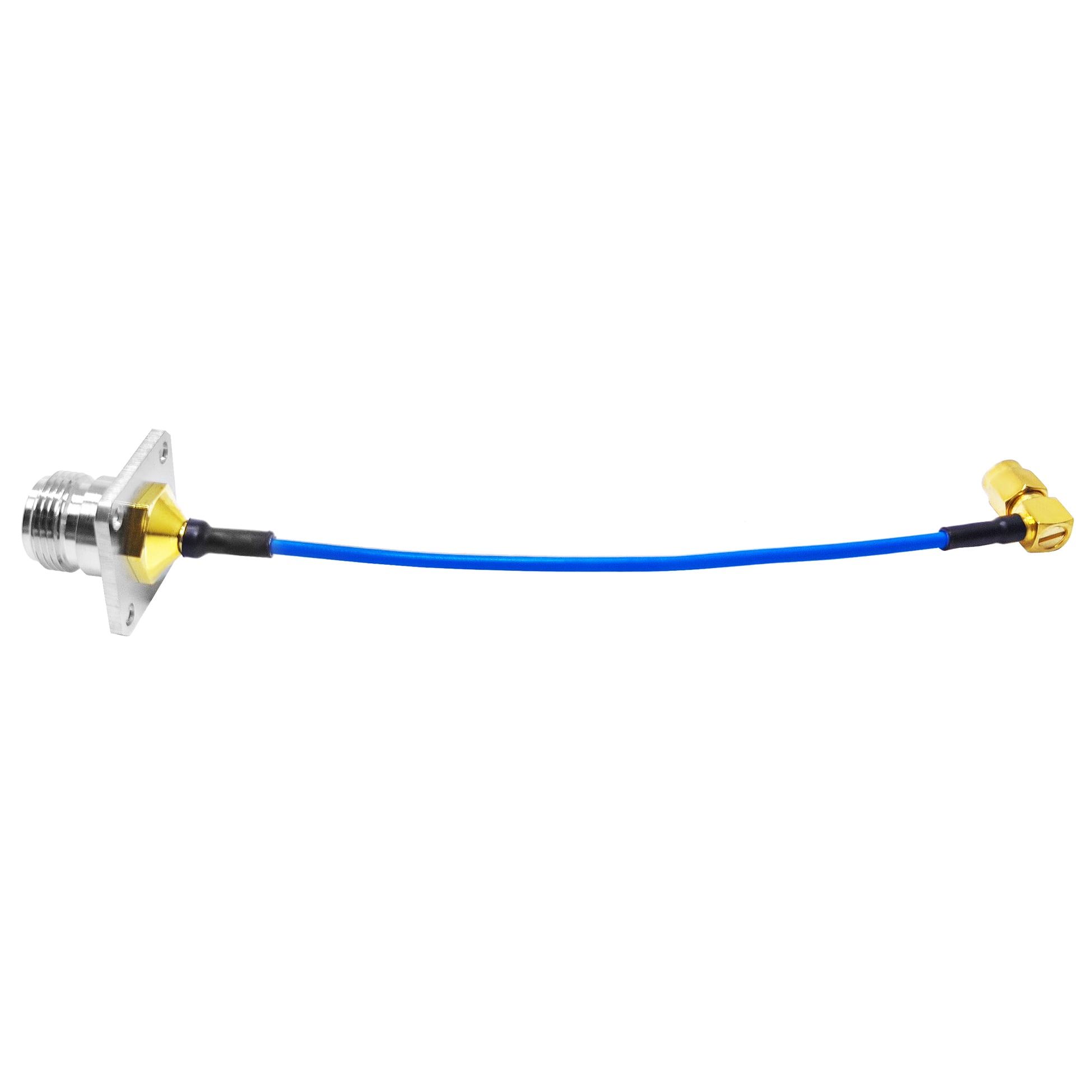
In deployments where consistent termination quality and assembly length matter—phased array test setups, surveillance trunk runs—a factory pre-terminated option removes in-field installation variability. The Worldpeak SS402 Pre-Terminated Cable Assembly provides a ready-to-deploy solution with verified insertion loss and VSWR performance, useful when shortening commissioning time or reducing skill variability is as important as the specification itself.
For bench through-connections between 50Ω instruments, a bnc male to bnc male cable using RG-58C/U or RG-316 is standard. Confirm both ends of a bnc male to bnc male cable are dimensionally matched to the cable OD and the crimp die specification before assembly. For interfacing a standard instrument port to a smaller embedded module, a bnc to smb cable is the common solution. The BNC side of any bnc to smb cable remains a standard 50Ω selection; the SMB connector frequency and impedance specification becomes the limiting factor for the assembly.
Worldpeak produces RF connectors and coaxial assemblies covering DC through 18 GHz across BNC and other standard interfaces, with pre-shipment insertion loss and VSWR sweep verification included for cable assembly orders. For integrators who need incoming inspection data without a separate characterization step, that test documentation reduces the workload at arrival.





