 EN
EN

BNC Connector Types: Reverse-Polarity and Variants
Early in my RF system work, I optimized connector selection around frequency range alone. The blind spot was polarity variant: a shipment of standard BNC arrived for a WiFi system that required reverse-polarity interfaces. Understanding all bnc connector types before specifying avoids that costly mismatch.
BNC connectors—originally designed in 1944—remain one of the most widely deployed RF connector families in communications, broadcast, industrial automation, military electronics, and test-and-measurement equipment. Their quick-disconnect bayonet coupling, reliable electrical performance from DC to 4 GHz, and availability across multiple variants make them suitable across a wider range of applications than most engineers initially realize. This guide covers the principal bnc connector types, their structural differences, core electrical parameters, and the application environments where each variant is the right selection.
Standard BNC: 50Ω and 75Ω Variants
The two most fundamental distinctions in standard BNC are impedance: 50Ω and 75Ω. The 50Ω version is specified for RF signal work and is the dominant choice in communications, test equipment, and industrial control systems. The 75Ω version is optimized for video signal transmission, where it matches the characteristic impedance of standard broadcast and CCTV cable plants.
Typical electrical parameters for standard BNC:
- Frequency range: 50Ω rated DC to 4 GHz; 75Ω rated DC to 2 GHz
- Voltage rating: 500 V RMS max continuous; dielectric withstanding voltage 1500 VRMS max
- Mating mechanism: Bayonet quarter-turn coupling
- Common cable types: RG-58 (50Ω), RG-59/RG-6 (75Ω)
Before you move to more specialized bnc connector types, ask yourself: is my application strictly below 4 GHz with standard voltage levels? If yes, the standard BNC is typically the lowest-cost and most easily sourced option.
Reverse-Polarity BNC (RP-BNC)
The reverse-polarity BNC—or RP-BNC—is structurally identical to standard BNC except for one deliberate change: the inner contact gender is swapped. A standard BNC male has a center pin; an RP-BNC male has a center socket. This means standard BNC and RP-BNC connectors are physically mating-incompatible, which is the entire design intent.
RP-BNC connectors exist primarily for regulatory compliance. FCC Part 15 and similar regulations in other markets require consumer wireless equipment—including many WiFi routers and WLAN access points—to use non-standard interfaces that prevent end users from connecting higher-gain antennas that would violate their device's authorization. RP-BNC provides that intentional incompatibility while maintaining standard BNC outer dimensions and bayonet coupling.
Key parameters for RP-BNC:
- Frequency range: DC to 4 GHz (standard models); extended-range designs reach DC to 12 GHz
- Impedance: 50Ω
- Primary application: IEEE 802.11 WLAN equipment, consumer routers, access points
- Mating compatibility: Only mates with RP-BNC counterpart; will not mate with standard BNC
An avoidable integration delay I've observed more than once involves connector polarity ambiguity. A procurement order specifying "BNC connector" without distinguishing standard vs. reverse-polarity results in mismatched assemblies that arrive on site with no mating counterpart. Specifying the polarity explicitly is a step that experienced procurement teams have long since added to their RF connector RFQ templates.
HD-BNC: High-Density BNC for Broadcast and Video
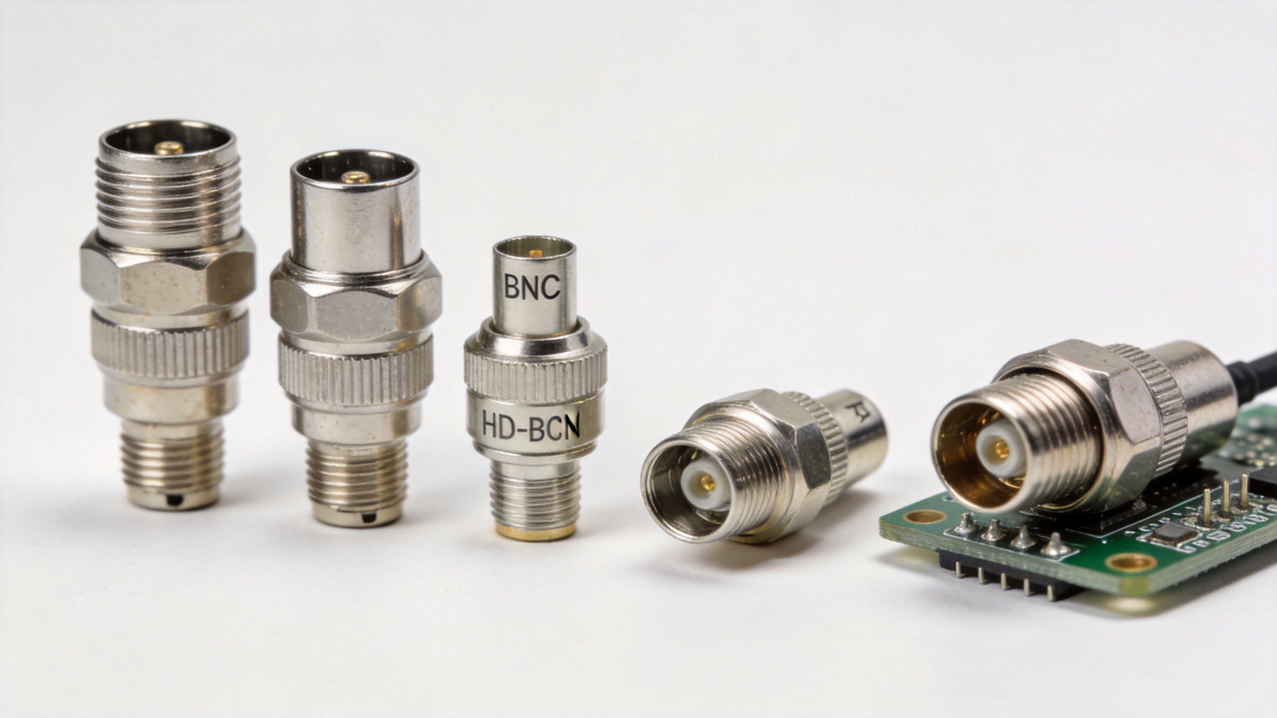
The HD BNC connector (high-density BNC) is a miniaturized variant developed to support high-bandwidth video applications—specifically HD-SDI, 3G-SDI, and 12G-SDI broadcast signal chains. It uses the same bayonet locking concept as standard BNC but in a smaller form factor that allows higher panel density and supports higher frequencies.
HD BNC connector parameters:
- Impedance: 75Ω (optimized for broadcast video)
- Frequency range: DC to 6 GHz for standard HD-BNC; 12G-SDI models rated to 12 GHz
- Standard support: SMPTE-compliant for professional broadcast equipment
- Application: Camera systems, production switchers, broadcast infrastructure, 4K and 8K video transmission
If your application involves professional broadcast video or any SDI signal chain, a standard BNC may work for HD-SDI (1.485 Gbps), but will reach its limits in 3G-SDI and will not reliably support 12G-SDI. Using an HD BNC connector rated to 12 GHz in those higher-bandwidth positions protects signal integrity as the video infrastructure scales up.
High-Voltage BNC Connectors
The high voltage BNC connector category addresses a specific limitation of standard BNC: its 500V continuous rating. Standard BNC connectors are typically rated for 500 V RMS max continuous and 1500 VRMS dielectric withstanding voltage—suitable for most communications and test applications, but insufficient for nuclear instrumentation, high-energy physics equipment, pulse generators, and certain oscilloscope probe interfaces where voltages routinely exceed those limits.
High voltage BNC variants include the SHV (Safe High Voltage) connector, which uses a reverse-polarity contact configuration to prevent connection to standard BNC systems, and other ruggedized designs rated from 1,000V to 5,000V. Roughly speaking, each step up in voltage rating involves increased dielectric spacing or modified contact geometry—so dimensions grow with voltage. Actual ratings must be confirmed against the specific high voltage BNC connector datasheet before use in safety-critical applications.
Typical high voltage BNC applications include:
- Nuclear and particle physics instrumentation
- High-power pulse measurement systems
- Medical imaging equipment power supplies
- Oscilloscope probes for industrial power electronics
Solder BNC Connectors for Precision and PCB Applications
The solder BNC connector is a termination variant rather than an electrical variant—it refers to BNC connectors designed for PCB-mount or cable termination by soldering, as opposed to crimp, compression, or twist-on attachment methods. Solder BNC connectors are commonly used in precision test equipment, laboratory instruments, and military electronics where the highest mechanical bond integrity between the connector and its mounting surface is required.
Key characteristics of solder BNC connectors:
- Termination method: Soldered to PCB or to cable conductor using controlled-process soldering
- Mechanical advantage: Highest pull-strength and vibration resistance among BNC termination methods when properly soldered
- Application environments: Laboratory test setups, precision measurement instruments, PCB-integrated RF front ends, military electronics where MIL-STD-348 compliance is required
- Dimensional tolerance: Precision-grade solder BNC connectors may be manufactured to tighter dimensional tolerances than commercial crimp types, supporting lower and more consistent contact resistance
For applications where MIL-STD-348 compliance and tight dimensional tolerances are required, solder BNC connectors are typically specified alongside precision-grade body materials such as stainless steel.
BNC Connector Types: Quick-Reference Comparison
| Type | Impedance | Frequency | Voltage Rating | Primary Application |
|---|---|---|---|---|
| Standard BNC 50Ω | 50Ω | DC–4 GHz | 500 VRMS | RF communications, test equipment, industrial |
| Standard BNC 75Ω | 75Ω | DC–2 GHz | 500 VRMS | Video, CCTV, broadcast infrastructure |
| RP-BNC | 50Ω | DC–4 GHz (to 12 GHz extended) | 500 VRMS | WLAN/WiFi regulated equipment |
| HD-BNC | 75Ω | DC–6 GHz (12G models to 12 GHz) | Standard | HD/4K/8K broadcast video (SDI) |
| High-Voltage BNC | 50Ω | DC–50 MHz (varies) | 1,000–5,000V+ | Nuclear, pulse, medical, power electronics |
| Solder BNC | 50Ω or 75Ω | DC–4 GHz+ | 500 VRMS | PCB mount, precision lab, military |
Selecting the Right BNC Variant: Application Decision Guide
The right choice among bnc connector types depends on the intersection of your frequency requirement, impedance standard, voltage environment, and application-specific regulatory or form-factor constraints. There is no single optimal BNC variant—the correct selection depends on the signal type and the environmental and regulatory context of your installation.
- If your application is below 4 GHz, standard RF signal path (50Ω), and no special voltage or polarity requirements: standard 50Ω BNC.
- If your application involves CCTV, HDTV, or sub-3G-SDI broadcast video: standard 75Ω BNC or HD BNC connector for higher bandwidth video.
- If your device is a WLAN/WiFi product subject to FCC Part 15 or equivalent antenna restrictions: RP-BNC.
- If you are designing for 12G-SDI, 4K broadcast, or Ultra-HD production infrastructure: HD BNC connector rated to 12 GHz.
- If your signal environment includes voltages exceeding 500V: high voltage BNC connector or SHV variant appropriate to your actual voltage level.
- If your application is a precision test instrument, PCB-integrated RF front end, or military electronics platform requiring MIL-STD-348 compliance: solder BNC connector with precision-grade dimensional tolerances.

For military, test-and-measurement, and precision procurement applications where solder BNC connectors with controlled dimensional tolerances and stainless steel body construction are required, the BNC-ULTRA100 Precision BNC Connector offers 50Ω impedance with ±0.02 mm dimensional tolerance, stainless steel body construction, and MIL-STD-348 compliance. This level of dimensional control reduces contact resistance variability across mating cycles and supports the documentation traceability requirements of military and regulated procurement processes.
Matching the right bnc connector types to your impedance, frequency, voltage, and regulatory requirements at the specification stage avoids the field delays that result from ordering the wrong variant.





