 EN
EN

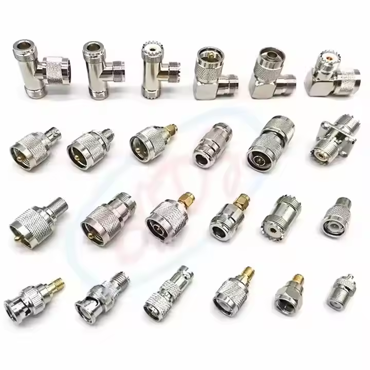
A low-profile rf adapter often carries disproportionate risk in high-frequency measurement setups, outdoor wireless infrastructure, and automated test environments. While physical mating between two distinct interconnect interfaces is easy to achieve, maintaining systemic 50-ohm impedance, low insertion loss, and predictable return loss requires a strict engineering approach. Choosing an adapter purely as an afterthought once the main transmission line is laid frequently introduces unwanted signal reflections, phase inaccuracies, and premature mechanical wear.
Systemic performance relies on evaluating the lowest-rated connector end, checking mechanical loading constraints, and confirming frequency headroom long before finalizing a bill of materials.
Signal Preservation Across Mixed Interconnect Standards
In any high-frequency path, a coax to rf adapter acts as an impedance-matched bridge connecting distinct transmission lines, test ports, or radio modules. Modern high-density enclosures frequently mix micro-miniature board interfaces with ruggedized chassis outputs. Without precision internal machining and proper dielectric alignment, this transitional junction becomes a prime source of impedance discontinuity.
System designers must evaluate the combined impact of every joined interface. A precision rf adapter cannot compensate for poor termination practices on adjacent rf cables, nor can it bypass the mechanical limits of an undersized housing. For critical instrumentation, aerospace telemetry, and outdoor cellular small cells, evaluating the insertion loss and VSWR profile across the entire operating spectrum is non-negotiable.
Comparative Performance Analysis of Common Adapter Transitions
SMA to N-Type Configurations
Transitioning from a compact board connector to a ruggedized external feeder commonly involves an SMA to N-type rf adapter. Standard brass SMA components typically operate up to 18 GHz, whereas baseline N-type interfaces operate reliably to 11 GHz, with precision extended-range variants reaching 18 GHz. The upper frequency limit of the assembled transmission path is strictly defined by the lowest-rated mating interface in the signal chain.
When deploying an SMA to N-type rf adapter outdoors, environmental sealing, panel mounting thickness, and mating torque become crucial. In heavy-vibration environments, using an unanchored N-type connection attached directly to a small SMA bulkhead can cause mechanical stress, distorting internal pin contacts and causing intermittent signal dropout.
SMA to BNC Transitions
The combination of SMA and BNC interfaces appears regularly in service benches, lower-frequency test fixtures, and legacy broadcast setups. The primary advantage of a BNC connector lies in its quick-locking bayonet mechanism. However, standard BNC interfaces exhibit significant impedance variation above 3 GHz or 4 GHz, making them unsuitable for high-frequency microwave testing where tight reflection margins are required.
Furthermore, mechanical compatibility must never be confused with electrical compatibility. Using a 75-ohm BNC component within a 50-ohm communications architecture damages center contacts and introduces massive reflection losses. Verifying structural alignment and dielectric spacing before placing an SMA to BNC rf adapter into service prevents costly system re-calibrations.
MMCX to SMA Board Level Interfaces
Connecting ultra-compact PCB assemblies to external measurement equipment often calls for an MMCX to SMA coax to rf adapter. MMCX connectors use a snap-on retention ring optimized for tight spatial footprints. However, they are inherently sensitive to side-loading forces and axial cable pull.
When high-flexure rf cables are routed directly from an MMCX interface without external strain relief, the snap-on contact quickly deteriorates. Applying lightweight, flexible pigtails and anchoring the transition point to a rigid enclosure frame stabilizes electrical contact resistance and extends overall operating life.
Electrical, Thermal, and Mechanical Selection Criteria
Evaluating frequency range and power capability requires two independent engineering checks. Power handling decreases significantly as operating frequency, ambient temperature, and altitude rise, due to dielectric heating and reduced voltage breakdown thresholds.
| Critical Parameter | Engineering Risk | Verification Requirement |
| System Impedance | Mismatch causes signal reflections and power loss | Verify 50-ohm or 75-ohm rating across all mated interfaces |
| Frequency Bandwidth | Path performance drops to the lowest-rated interface | Review full VSWR and return loss sweep data up to max frequency |
| Power & Thermal Limits | Dielectric heating degrades unrated components | Factor in duty cycle, peak power, and ambient derating metrics |
| Mechanical Life | Contact wear increases insertion loss over time | Establish clear torque limits and mating cycle tracking protocols |
Integrating Adapters with Connectors and Cable Assemblies
An rf adapter does not function in isolation; its performance is linked directly to the surrounding rf connectors and high-frequency rf cables. In complex microwave harnesses, accumulating tolerances between multiple adapters can alter phase stability and introduce unexpected resonances.
For automated test setups and commercial production lines, maintaining consistent assembly standards is vital. Utilizing identical rf connectors, calibrated torque wrenches, and uniform inspection workflows across all interconnect lines simplifies trouble-shooting. When tracing high VSWR, checking the inner contact pin depth and dielectric seating on the coax to rf adapter frequently isolates the issue before replacing entire cable runs.
Quality Control and B2B Procurement Standards
Procuring high-frequency passive components requires rigorous drawing controls, material verification, and continuous batch testing. Commercial catalog descriptions often obscure variations in center contact plating, body threading, and PTFE dielectric quality. High-reliability applications demand clear lot traceability, gold-plating thickness verification, and consistent dimensional tolerance checks.
Standard incoming inspection workflows should combine visual checks of threads and center pins, mechanical fit-checks against calibrated gauge blocks, and vector network analyzer (VNA) sweep sampling across the specified bandwidth. Partnering with a dedicated manufacturing source ensures that mass-produced components maintain the tight tolerance standards established during initial prototype sampling.
Essential Procurement Checklist for System Integration
-
Define both interface standards, gender, polarity, and body geometry (straight or right-angle).
-
Establish the precise system operating frequency range and target VSWR/return loss figures.
-
Outline continuous wave (CW) power requirements, peak power thresholds, and operating temperature ranges.
-
Confirm cable assembly routing, panel bulkhead mounting needs, and strain relief placement.
-
Request detailed dimensional drawings, plating material certifications, and RF test reports.
-
Align on sampling plans, lot inspection standards, and batch traceability protocols before volume release.
Precision Manufacturing and Global Supply Infrastructure
Selecting the right microwave interconnect solution requires balancing electrical performance, mechanical robustness, and long-term production availability. Worldpeak provides custom and standard RF interface solutions engineered for demanding communications, industrial test, and outdoor broadcast environments.
With advanced CNC machining capabilities, rigorous plating quality controls, and comprehensive VNA testing across broad frequency bands, Worldpeak delivers reliable interconnect hardware tailored to global OEM and B2B requirements. Aligning signal specifications with disciplined manufacturing ensures every production harness and test bench performs consistently under real-world conditions.





