 EN
EN

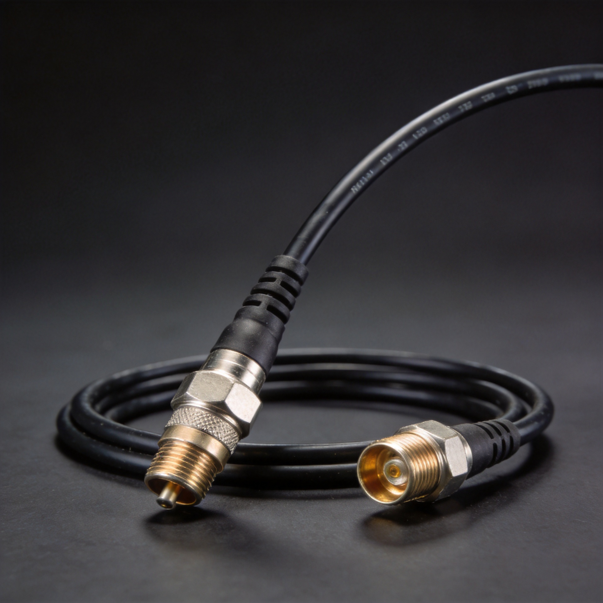
Coaxial Cable Cord: Flexible RF Jumper Applications
Specifying a coaxial cable cord for a flexible RF jumper is rarely as straightforward as picking a diameter. The structural choices baked into a cable (conductor material, dielectric type, shielding architecture, and jacket compound) determine whether a jumper survives five years of rooftop thermal cycling or develops intermittent loss faults within months. Across base station antenna systems, laboratory setups, and in-building distributed antenna networks, the selection logic that holds up most consistently is: match the cable's electrical and mechanical properties to the installation environment first, then work backward to connector compatibility.
Anatomy of a Coaxial Cable Cord
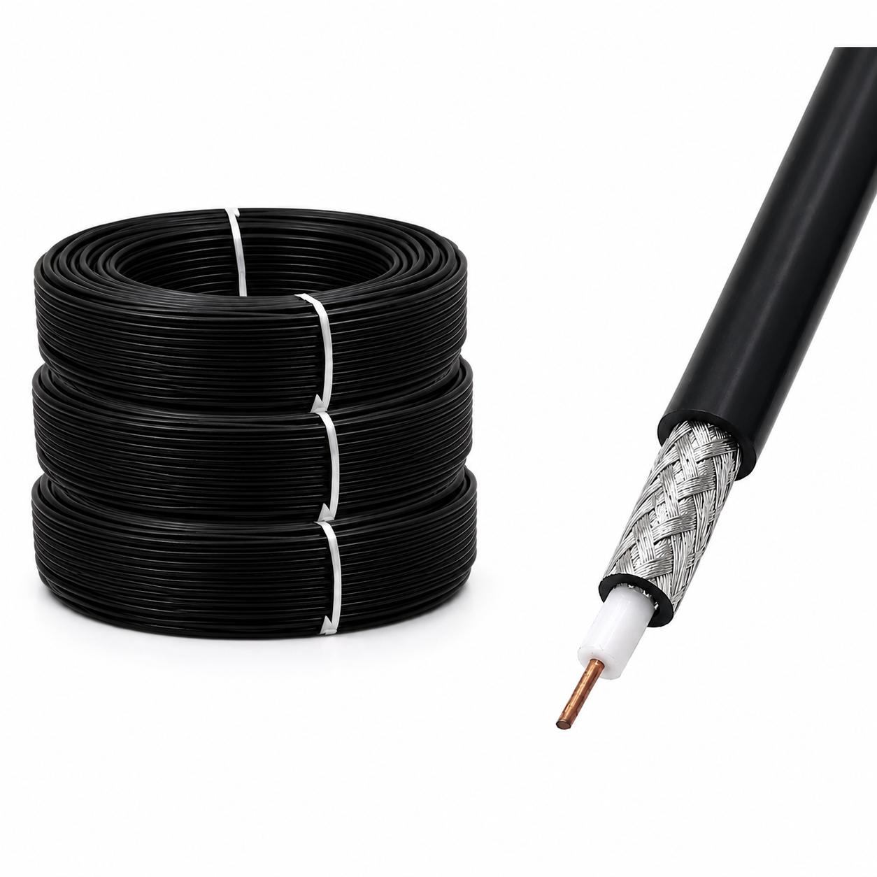
A coaxial cable cord is built around four concentric layers with distinct functions. The inner conductor — solid copper, stranded copper, or copper-clad steel — carries the RF signal. The dielectric spacer, which may be solid polyethylene (PE), foamed PE, or PTFE, sets the electrical velocity of propagation and contributes significantly to attenuation. The outer conductor or shield intercepts radiated interference and, in flexible assemblies, usually takes the form of a braided copper layer, an aluminum foil plus braid combination, or a corrugated copper tube in semiflexible designs. The outer jacket — PVC for indoor use, PE or LSZH for outdoor and plenum applications — protects against abrasion, UV exposure, and moisture ingress.
The quality of each layer affects the two metrics that matter most in procurement: insertion loss per unit length and shielding effectiveness. A cable with a poorly controlled dielectric geometry will show attenuation that drifts across the frequency band, which is particularly problematic for wideband RF systems operating from 400 MHz through 6 GHz. Shielding effectiveness below 85 dB is generally insufficient for installations near cellular equipment radiating at high power levels.
50Ω vs 75Ω: The Impedance Selection Decision
The 50Ω vs 75Ω split is one of the first decisions a procurement engineer encounters, and it deserves a clear-headed treatment. The 50Ω standard emerged as a practical engineering compromise: for an air-dielectric coaxial line, the impedance that maximizes power handling is roughly 30Ω, while the impedance that minimizes signal loss is approximately 77Ω. The geometric mean of these two sits near 48Ω, and 50Ω was standardized as the rounding that balanced both objectives.
The 75Ω standard has a different origin. It closely matches the minimum-loss impedance for low-cost dielectric materials used in consumer cables and was established decades before CATV infrastructure became widespread. Today, 75Ω coaxial cable cord is standard for video distribution, CATV head-end interconnects, and broadcast signal routing. For RF communication infrastructure including cellular base station antenna feeders, distributed antenna system (DAS) cabling, industrial wireless, and laboratory RF test setups, 50Ω is the correct impedance. Mixing impedances introduces reflections that degrade return loss and create standing-wave patterns that reduce effective radiated power.
In practical terms: if your system uses SMA, N-type, TNC, or RP SMA connectors, you are almost certainly working in a 50Ω environment. If you are integrating with 75Ω F-type or DIN 1.0/2.3 infrastructure, verify the source impedance before ordering cable cord stock.
Cable Type Comparison: Matching Performance to Application
The table below summarizes the key electrical parameters for the most common 50Ω flexible coaxial cable cord types encountered in professional RF installations. Attenuation values are approximate and vary by manufacturer's dielectric specification.
| Cable Type | OD (approx.) | Attenuation @ 450 MHz (dB/100 ft) | Power @ 450 MHz (W) | Typical Use Case |
|---|---|---|---|---|
| RG58 | ~4.95 mm | ~10.6 | ~80 | Short bench jumpers, test leads, indoor patch cabling |
| RG59 | ~6.15 mm | ~9.5 (75Ω) | ~100 | Video and CATV signal distribution (75Ω system) |
| RG213 | ~10.3 mm | ~5.1 | ~300 | Medium-run outdoor antenna feeders, amateur radio, base station jumpers |
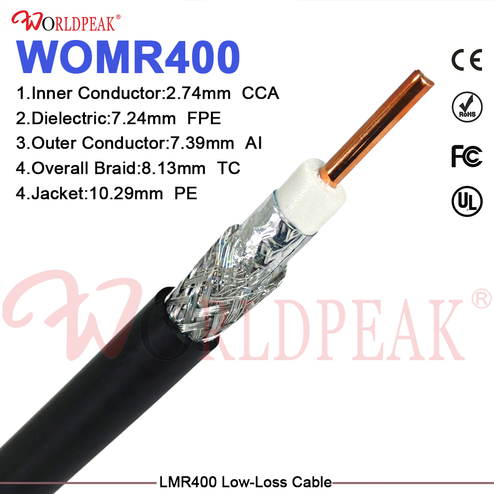
| LMR400 | ~10.3 mm | ~2.7 | ~550 | Long-run low-loss outdoor feeders, DAS trunks, cellular antenna connections |
RG58 remains the most cost-effective option for short indoor jumpers where cable runs stay under three meters and signal loss at lower frequencies is acceptable. Its small diameter and good flexibility make it well suited for test bench environments and rack-mounted equipment connections. At 450 MHz, however, its ~10.6 dB/100 ft attenuation limits useful run lengths to under 10 meters for loss-budget-constrained systems.
RG213 offers a meaningful improvement: with attenuation near 5.1 dB/100 ft at 450 MHz and a power rating around 300W at the same frequency, it is the practical choice for outdoor antenna base jumpers, rooftop sector antenna connections, and feeder runs up to 20–30 meters where LMR400 pricing is not justified. Its thicker braid shielding also provides superior mechanical protection compared to RG58 in outdoor conduit installations.
For longer feeder runs and system architectures where every decibel of link budget matters, LMR400-equivalent low-loss cable provides roughly half the attenuation of RG213, approximately 2.7 dB/100 ft at 450 MHz, with a power handling advantage that matters in high-power cellular transmit paths. Worldpeak's LMR400 Low-Loss 50 Ohm Coaxial Cable is qualified for these applications and is available with pre-tested insertion loss documentation for incoming inspection use.
For installations where thinner gauge cable is required for the signal distribution segment, the Worldpeak RG196 50-Ohm Coaxial Cable provides engineering-level selection data to help buyers confirm the right specification for each run length and frequency band.
Indoor vs Outdoor Installation Considerations
The key variable differentiating indoor and outdoor coaxial cable cord procurement is jacket material and connector sealing. Indoor PVC jackets are not UV stabilized; deploying them outdoors accelerates jacket embrittlement and cracking. Outdoor-rated PE jackets resist UV degradation, while LSZH variants meet fire safety requirements for building riser and plenum spaces.
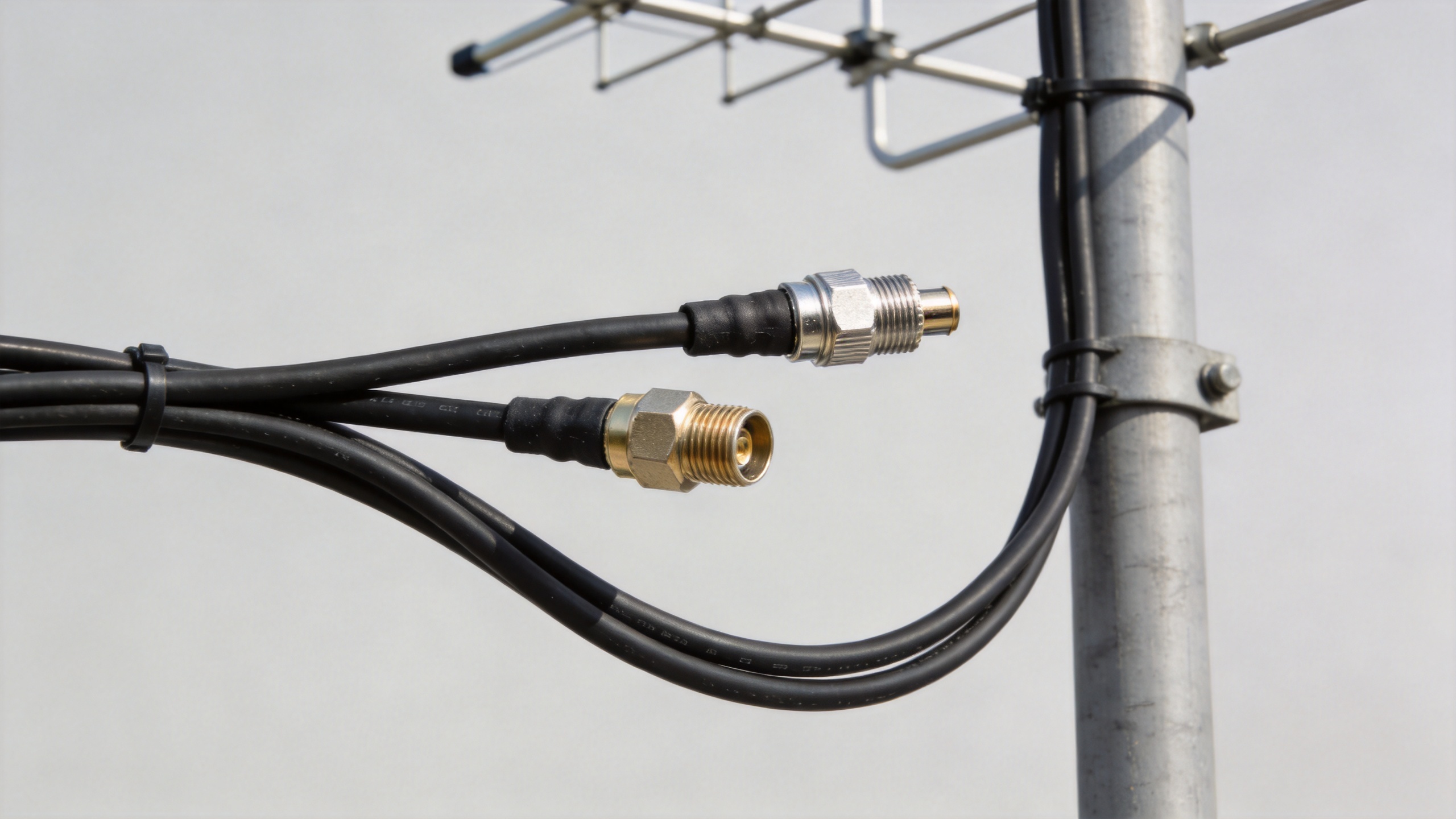
Connector-to-cable interface sealing deserves equal attention. At every point where the braid is exposed for connector termination (SMA, N-type, RP SMA, TNC), water ingress through capillary action along the braid strands can migrate meters back from the connector face, oxidizing the inner conductor and dramatically raising insertion loss over time. Specifying assemblies with weatherproofing tape or heat-shrink boots at the connector-cable interface is standard practice for outdoor jumpers. Worldpeak's outdoor-rated feeder cable assemblies integrate this weatherproofing at the connector interfaces, reducing the risk of moisture-related faults in tower, rooftop, and mast installations.
Minimum Bend Radius and Mechanical Routing
Flexible coaxial cable cord assemblies have minimum bend radii below which the inner conductor can shift, permanently altering impedance at the bend point. For RG58, typical minimum bend radius is 12–15 mm for dynamic flex and 25–30 mm for static routing. LMR400 and RG213-diameter cables require 35–50 mm for static routes and 100 mm or more for repeated flex.
In rack installations and cable management trays where jumpers are routed in tight radii, exceeding the minimum bend radius is a common source of return loss degradation that is difficult to diagnose without a vector network analyzer. Specifying pre-formed jumpers with appropriate strain relief at each connector minimizes this risk during installation and over the service life of the system.
Procurement Checklist for RF Jumper Cable Cord
- Confirm system impedance: 50Ω or 75Ω. For RF communication infrastructure, 50Ω is standard; 75Ω is correct only for video/CATV distribution paths.
- Select cable type based on run length, frequency band, and acceptable loss budget. RG58 for short indoor runs; RG213 for medium outdoor runs; LMR400-type for long low-loss feeders.
- Specify jacket compound for the installation environment: PVC for indoor-only, PE or LSZH for outdoor or riser/plenum routes.
- Confirm connector interface type and impedance: SMA (50Ω), RP SMA (50Ω, reverse polarity shell), N-type (50Ω or 75Ω), BNC, TNC, or 7/16 DIN as required by your system.
- Verify pre-shipment test documentation availability: insertion loss and VSWR sweep records reduce incoming inspection overhead for quality-critical infrastructure projects.
- For outdoor assemblies, confirm connector weatherproofing specification at each interface before order placement.
Sourcing coaxial cable cord assemblies from a supplier with direct production capability across SMA, N-type, BNC, TNC, and RP SMA interfaces allows system integrators to consolidate multi-interface procurement and maintain consistent electrical documentation across mixed-connector installations — a practical advantage when managing incoming inspection across large infrastructure projects.





