 EN
EN

What environmental resistance can be customized for OEM rf cable
2026/09/25
Customize an rf high frequency cable for temperature, moisture, corrosion, vibration, flexing, and OEM validation needs.
2026/09/11
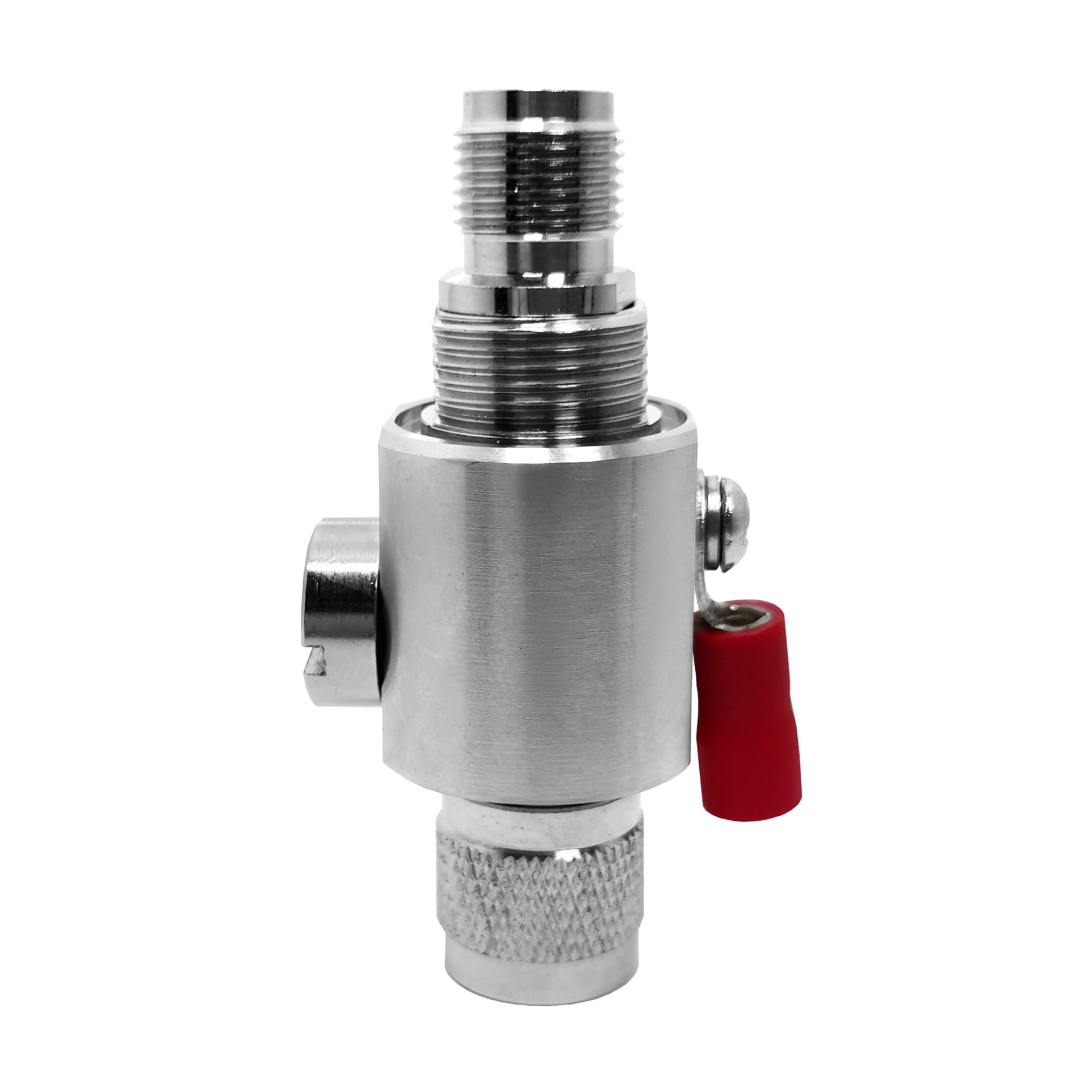
When configuring modern high-frequency wireless equipment, selecting the correct SMA connectors is paramount for maintaining signal integrity, mechanical durability, and low insertion loss. As an essential component within any robust antenna system connectors lineup, SubMiniature version A interfaces provide dependable microwave performance up to 18 GHz (and up to 26.5 GHz for precision variants). Procurement engineers and RF designers sourcing components from WORLDPEAK must navigate a diverse array of physical polarities, mounting styles, and plating standards to ensure long-term reliability in harsh operating environments.
This technical selection guide breaks down critical design parameters, performance comparisons, and manufacturing quality controls required to optimize your next RF hardware deployment.
Selecting professional-grade SMA connectors begins with understanding their baseline mechanical and electrical tolerances. Governed by MIL-STD-348 and IEC 60169-15 standards, these 50-ohm threaded interfaces rely on a 1/4-36 UNS coupling nut mechanism that ensures secure engagement under heavy vibration.
| Performance Parameter | Standard SMA Specification | High-Performance Precision SMA |
|---|---|---|
| Characteristic Impedance | 50 Ohms | 50 Ohms |
| Frequency Range | DC to 12.4 GHz (Semi-rigid up to 18 GHz) | DC to 26.5 GHz |
| Voltage Standing Wave Ratio (VSWR) | ≤ 1.15 + 0.005 × f(GHz) | ≤ 1.05 + 0.005 × f(GHz) |
| Coupling Nut Torque Specification | 0.8 N·m to 1.1 N·m (7 to 10 in-lbs) | 0.8 N·m to 1.1 N·m with calibrated wrench |
| Durability (Mating Cycles) | ≥ 500 cycles | ≥ 500 cycles |
| Dielectric Withstanding Voltage | 1000 V RMS at sea level | 1000 V RMS at sea level |
A frequent procurement error in wireless communication builds involves confusing standard SMA connectors with Reverse Polarity (RP-SMA) variants. While both share the same outer 1/4-36 UNS threaded barrel, their internal contact gender is inverted to comply with FCC Part 15 regulations regarding intentional radiator antennas.
Procurement Warning: Specifying the wrong polarity results in physical incompatibility or zero signal transmission, leading to costly manufacturing line delays and project rework. Always verify mating interface blueprints before finalizing OEM batch orders.
Evaluating a factory partner's material compliance is vital for preventing galvanic corrosion and signal attenuation over time. High-performance RF connector selection requires careful auditing of base metals and surface platings:
To guarantee that every batch of coaxial connectors meets rigorous international telecommunications and industrial standards, production facilities execute a strict 4-step quality assurance workflow:
As a direct-to-market manufacturer,WORLDPEAK provides complete flexibility for system integrators and antenna manufacturers requiring tailored RF connector selection options:

2026/09/25
Customize an rf high frequency cable for temperature, moisture, corrosion, vibration, flexing, and OEM validation needs.

2026/09/25
Streamline RF equipment assembly lines with custom coaxial jumpers. Reduce line-side rework, ensure precise routing, and boost production efficiency.

2026/09/25
Learn PL-259 connector selection, soldering, weatherproofing, and RF applications for dependable antenna feedlines.

2026/09/25
Confirm impedance for a 90 degree coax connector with an ODM test plan covering VNA setup, VSWR, acceptance criteria, and release records.

2026/09/25
Learn when an n type coax connector can omit extra anti-corrosion treatment and when OEM exposure conditions require it.

2026/09/25
Learn how the custom cable and wire sample process helps ODM buyers validate design, testing, and production readiness.