EN

rf-connector/ez-series-solderless-clamp-rf-connectors218, rf-connector/ez-series-solderless-clamp-rf-connectors218, /ez-series
EN
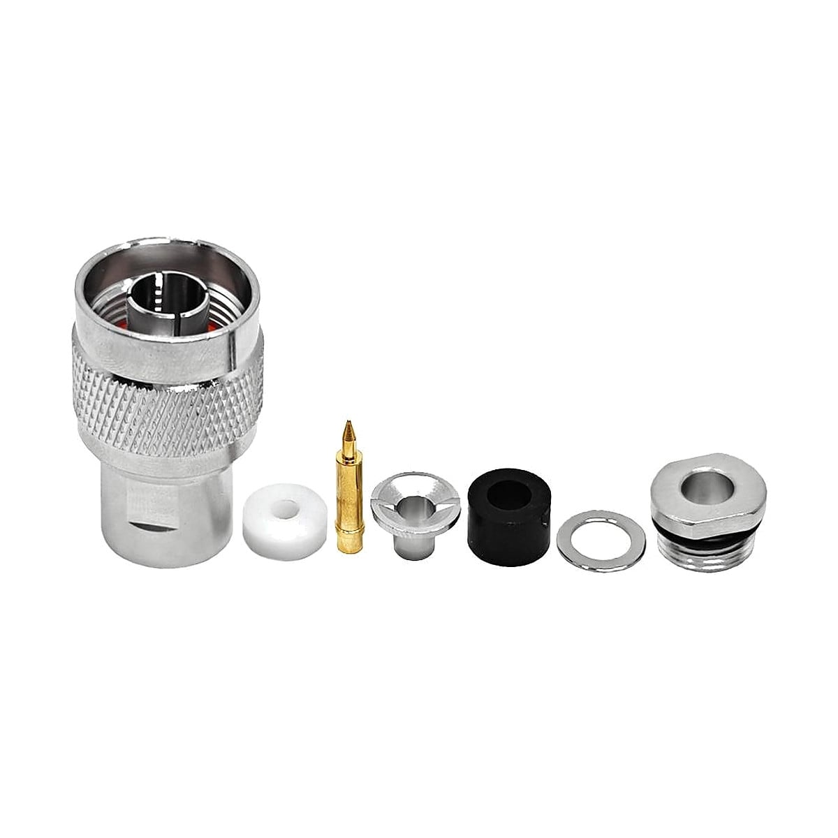
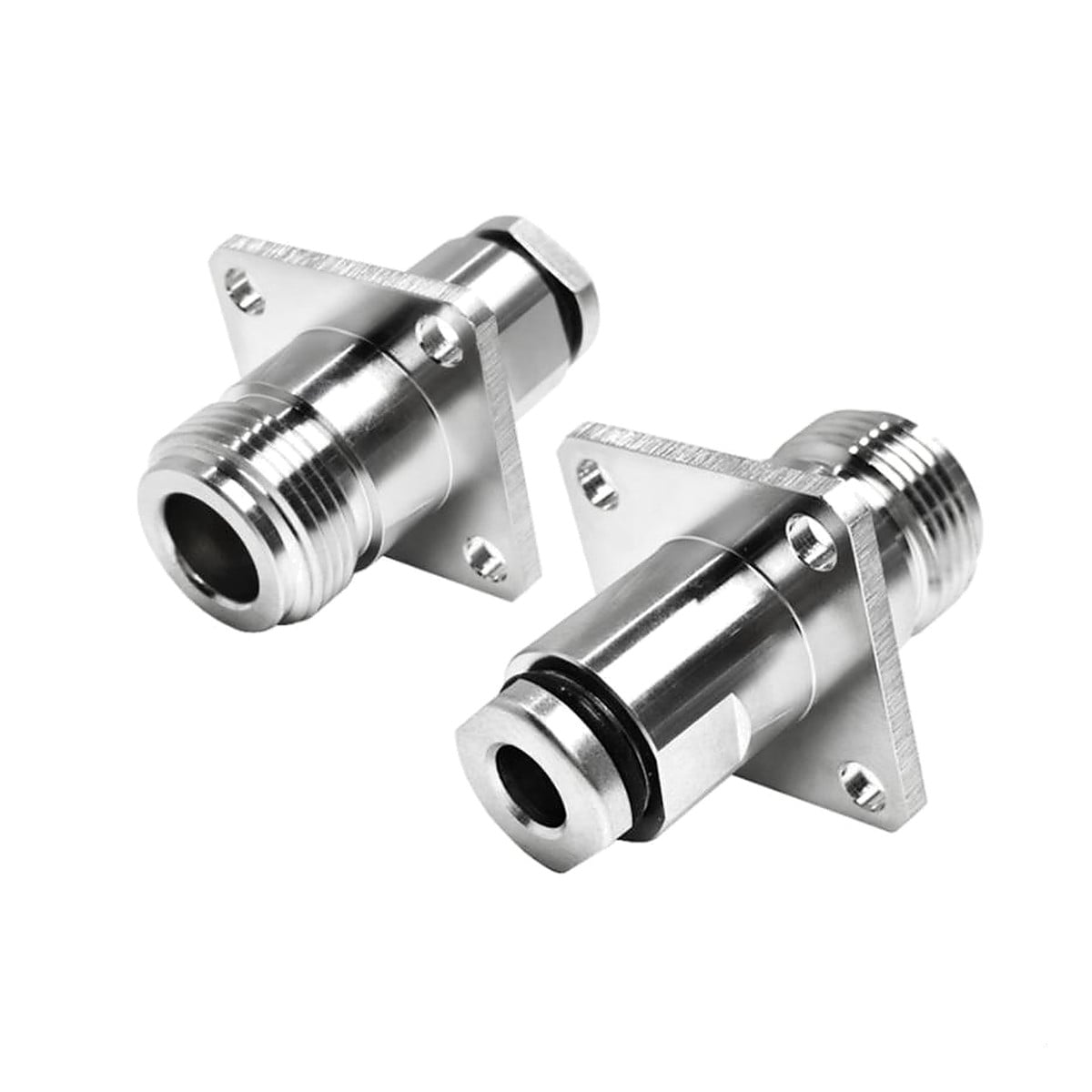
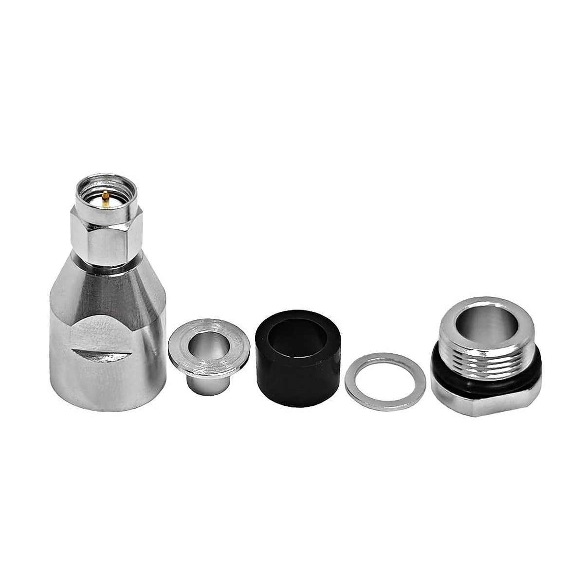
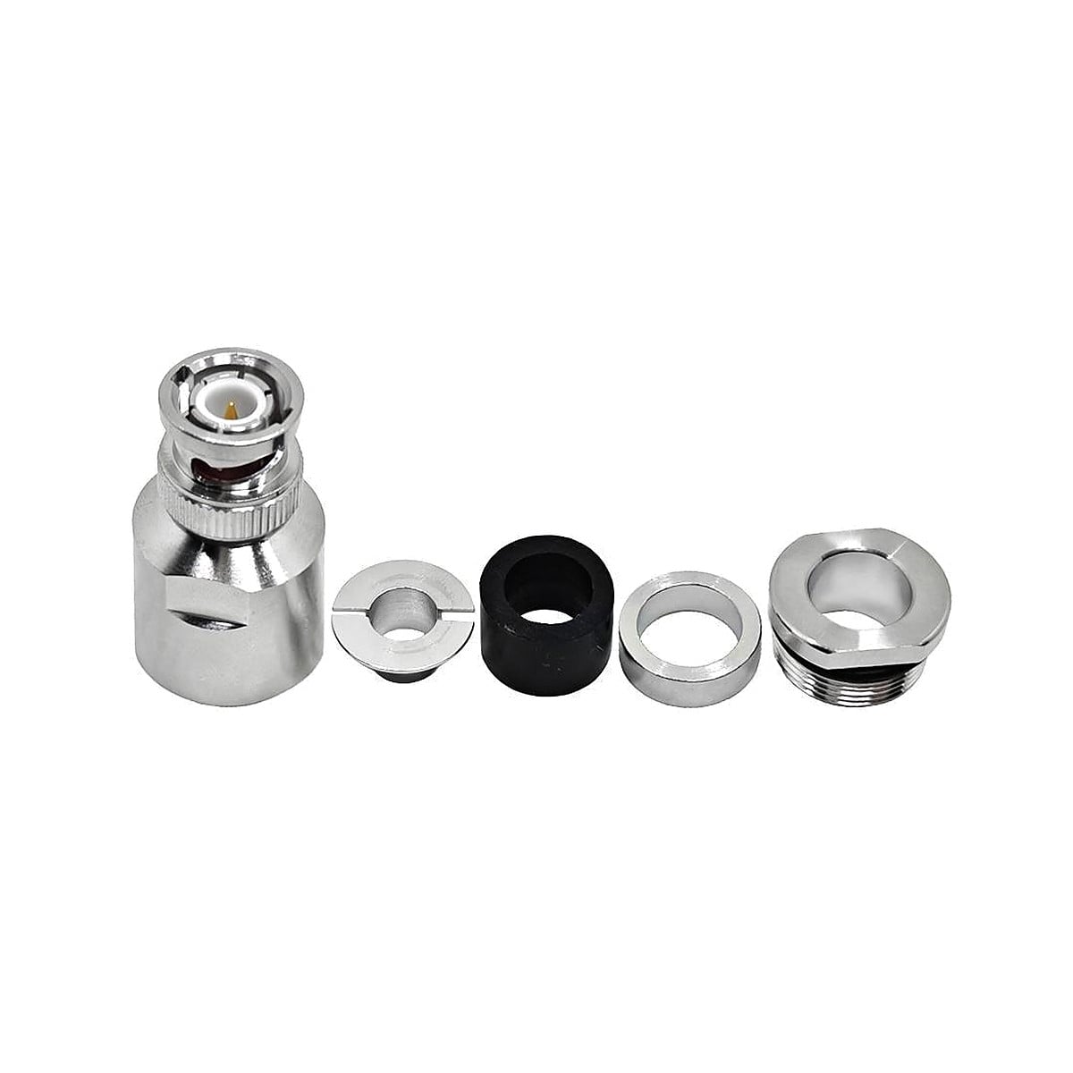
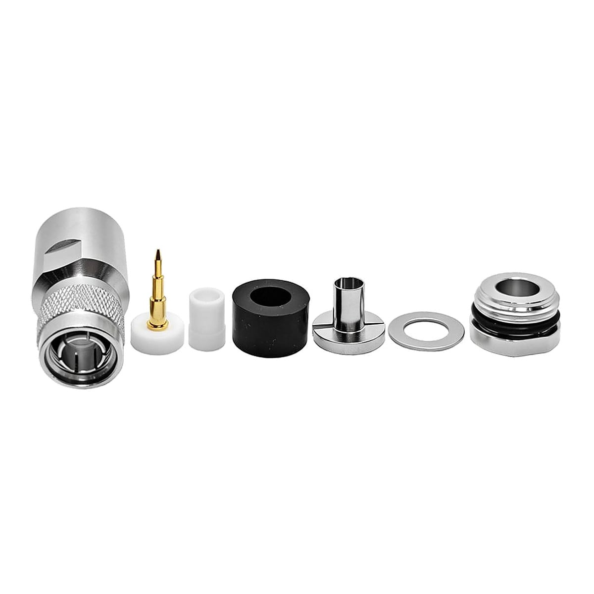
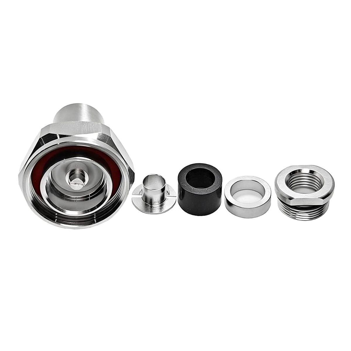
The EZ series uses a solderless centre-conductor termination and a clamp cable attachment. The range includes N-type, SMA, UHF, BNC, TNC, RP-TNC and 7/16 DIN configurations for different cable constructions. The detailed specification below uses one example: a straight, 50 Ω N-type male connector for LMR240 cable.
Parameter |
Specification |
Series |
EZ |
Interface range |
N-type / SMA / UHF / BNC / TNC / RP-TNC / 7/16 DIN |
Reference interface |
N-type male, straight cable connector |
Reference cable |
LMR240 |
Reference impedance |
50 Ω; confirm impedance for other cable versions |
Centre-conductor termination |
Solderless |
Cable attachment |
Clamp type |
Reference mating coupling |
Threaded N-type interface |
Reference frequency range |
DC–6 GHz |
The tables below list the configurations shown in the product catalogue. Cable names in one row identify version options, not interchangeable cables. Select the exact cable-specific contact, clamp components and body. Detailed electrical limits are provided only for the N male LMR240 reference configuration.
Interface and gender |
Cable versions listed |
Mounting form |
N-type male |
LMR240 / H155 / RG59 |
Cable mount |
N-type male |
LMR300 / 5D-FB / RG6 |
Cable mount |
N-type male |
LMR400 / RG8 / RG213 / RG214 |
Cable mount |
N-type male |
LMR500 |
Cable mount |
N-type female |
LMR400 / RG8-U / RG213 / RG214 / H1000 |
Cable mount |
N-type female |
LMR240 / H155 / RG59 |
Flange panel mount |
N-type female |
RG58 / LMR195 / RG223 / RG142 / RG400 |
Flange panel mount |
Interface and gender |
Cable versions listed |
Mounting form |
SMA male |
LMR300 / 5D-FB / RG6 |
Cable mount |
SMA male |
LMR400 / RG8 / RG213 / RG214 |
Cable mount |
Interface and gender |
Cable versions listed |
Mounting form |
UHF male (PL-259) |
LMR240 / H155 |
Cable mount |
UHF male (PL-259) |
LMR300 / LMR400 |
Cable mount |
UHF male (PL-259) |
LMR500 |
Cable mount |
UHF female (SO-239) |
RG58 / LMR195 / LMR200 / RG223 |
Cable mount |
UHF female (SO-239) |
LMR240 / H155 / RG59 |
Cable mount |
UHF female (SO-239) |
LMR300 / 5D-FB |
Cable mount |
Interface and gender |
Cable versions listed |
Mounting form |
BNC male |
Not specified in the catalogue |
Cable mount |
TNC male |
LMR300 / 5D-FB / RG6 |
Cable mount |
RP-TNC male |
LMR400 / RG8 / RG213 / RG214 / H1000 |
Cable mount |
7/16 DIN male |
LMR400 / RG8 / RG213 / RG214 / H1000 |
Cable mount |
Selection notes: check cable impedance as well as dimensions, particularly for entries listing RG6 or RG59. The BNC cable version is not identified in the catalogue and requires confirmation. RP-TNC identifies a reverse-polarity version; verify its contact arrangement against the part drawing.
The following data describe the N male clamp connector for LMR240 cable, drawing WT26D3.640.2629. The frequency range, VSWR, voltage ratings and materials must be checked separately for other EZ configurations. The values below are specification limits from the reference technical sheet, not measured results for an assembled cable.
Item |
Value |
Reference part |
N male clamp for LMR240 |
Drawing identifier |
WT26D3.640.2629 |
Overall length |
38.4 mm (catalogue outline) |
Parameter |
Value |
Impedance |
50 Ω |
Frequency range |
DC–6 GHz |
VSWR |
≤ 1.2 |
Withstand voltage |
2500 V rms |
Working voltage |
1500 V |
Contact resistance – centre |
≤ 1 mΩ |
Contact resistance – outer |
≤ 1 mΩ |
Insulation resistance |
≥ 5000 MΩ |
Parameter |
Value |
Temperature range |
−55 °C to +155 °C |
Durability |
> 500 mating cycles |
Part |
Base material |
Plating |
Body |
Brass |
Tri-metal plated |
Centre conductor |
Brass |
Gold plated |
Insulator |
PTFE |
— |
O-ring |
6146 silastic |
— |
Reference: N male clamp for LMR240 technical sheet, drawing WT26D3.640.2629; 38.4 mm outline shown in the product catalogue. Interface references listed on the sheet: IEC 60169-16 / MIL-C-39012 / CECC 22210. These references do not establish third-party certification.
EZ describes the cable termination design; it does not define a separate mating interface. N-type, SMA, UHF, BNC, TNC and 7/16 DIN have different mating geometries. Select the mating connector by interface, gender, polarity and impedance. The reference N male version mates with a compatible 50 Ω N-type female connector; another interface requires a suitable adapter or cable assembly.
The clamp termination and the threaded N-type mating coupling perform different functions. A solderless centre contact does not make the connector tool-free and does not remove the need for correct cable preparation.
Selection item |
Reference configuration |
Required check |
Scope |
Mating connector |
50 Ω N-type female |
Interface dimensions and gender |
Direct mating only with a compatible N-type interface |
Different interface |
Adapter or cable assembly |
Both interfaces, impedance and operating band |
No universal adapter rating is implied |
Cable substitution |
LMR240 is the reference cable |
Conductor, dielectric and jacket dimensions |
Similar outside diameter alone is insufficient |
Use the cable options in the model-range tables to select a configuration, then confirm the conductor, dielectric, shield and jacket construction against its drawing. LMR240 is the cable identified by the detailed reference part. A cable option listed for one model is not automatically suitable for another model.
Cable |
Selection basis |
LMR240 |
Reference cable for drawing WT26D3.640.2629 |
On this page, “solderless” refers to the centre-conductor termination and “clamp” describes the cable attachment. N-type, SMA, UHF, BNC, TNC and 7/16 DIN identify mating interfaces; PL-259 and SO-239 identify UHF male and female forms. RP-TNC denotes a reverse-polarity TNC version. The EZ series designation does not make these interfaces interchangeable.
The reference data apply to the connector configuration identified above. Cable loss, assembly workmanship and any additional adapters affect the completed connection and require separate assessment.
IP rating, insertion loss, PIM, power and assembly torque require separate part-specific data.
Q. Which connector configurations are included?
A. N-type male and female, SMA male, UHF male (PL-259) and female (SO-239), BNC male, TNC male, RP-TNC male and 7/16 DIN male. The model-range tables list the corresponding cable options and mounting forms.
Q. Does the centre conductor require soldering?
A. No. The EZ termination described here uses a solderless centre contact and a clamp cable attachment. Follow the instructions for the exact part.
Q. Which model supplies the parameters on this page?
A. The N male clamp connector for LMR240, drawing WT26D3.640.2629. Its specified impedance is 50 Ω and its frequency range is DC–6 GHz.
Q. Do these specifications apply to the entire EZ series?
A. No. Confirm the interface, cable, electrical limits and mechanical requirements for each selected configuration.
Identify the interface and gender, the exact cable type and construction, the operating band and the connector drawing when specifying an EZ termination. Use the part-specific drawing and assembly instructions for production or installation.