EN
EN

f-female-to-f-female-lightning-arrester---dc---3-ghz, f-female-to-f-female-lightning-arrester---dc---3-ghz, /rf-lightning-arrester
EN
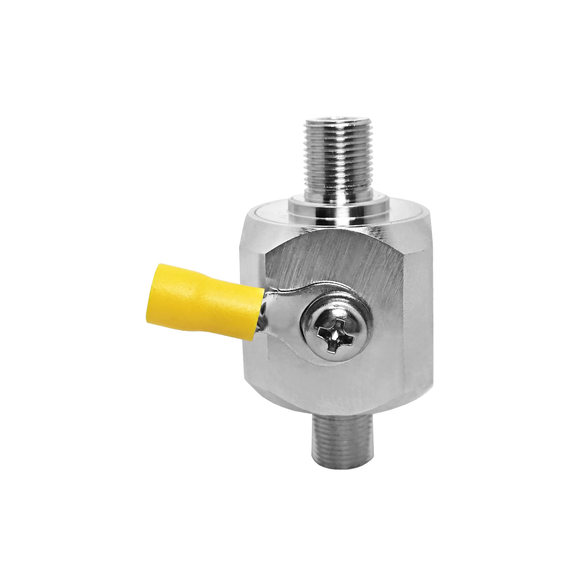
This F Female to F Female lightning arrester is a GDT based RF surge protector designed for DC - 3 GHz operation. It sits in the transmission line between the antenna and the radio equipment, diverting lightning-induced transients to ground before they reach the sensitive front end. The 75 ohm design holds insertion loss at 0.2 dB with a VSWR of 1.3 or better across the passband.
Request a Quote | Download Datasheet | Ask an Engineer
Product Overview
The F Female to F Female lightning arrester is designed for 75 ohm coaxial routes where a direct F-type inline connection and a dedicated surge-to-earth path are required. It supports a DC - 3 GHz passband and is suited to wall-plate entries, set-top box inputs, multiswitch installations, and similar distribution lines. A 90 V gas discharge tube is installed inside the body. During ordinary signal transmission, the tube stays in a high-impedance state so that RF energy continues through the F Female to F Female lightning arrester with a reference insertion loss of 0.2 dB.
If a lightning-related transient reaches the cable, the GDT changes from its normal non-conductive condition and sends the excess energy toward the ring-terminal ground connection. This F Female to F Female lightning arrester therefore works with, rather than independently from, the building or site earthing arrangement. The low-capacitance GDT design is useful for broadband coaxial paths, while its serviceable discharge component can be checked following a substantial event. A diode product may operate at a different threshold, but this lightning arrester is intended for systems that need low RF loading and an externally grounded surge path.
Protection Mechanism and Construction
Reference Technical Specifications
The following details identify the reference version of this F Female to F Female lightning arrester. Verify the final production configuration before treating the values as project-specific requirements.
| Parameter | Specification | Notes |
| Connector Interface | F Female to F Female | Standard RF connector |
| Mounting Style | Inline | Body configuration |
| Impedance | 75 ohm | System impedance |
| Frequency Range | DC - 3 GHz | Passband |
| Insertion Loss | 0.2 dB | Across passband |
| VSWR | 1.3 | Maximum |
| Power Handling | 60 W | CW, reference |
| Discharge Element | 90 V | Gas discharge tube |
| Surge Current | 10 kA (8/20 us) | 8/20 us waveform |
| Grounding | Ring terminal | M4 lug, ground wire |
| Body Material | Machined brass | Corrosion-resistant plating |
| Weight | 93.6 g | Approximate |
| Typical Application | Wall plate entry, STB input, multiswitch | Primary use case |
All figures shown are reference specifications for this protection family and should be confirmed for the selected configuration.
Engineering Comparison
Applications
Installation and Grounding Notes
OEM and B2B Support
FAQ
Q: When should the gas discharge tube be inspected?
A: Inspect or test the 90 V tube after a significant surge event. If leakage or hold-off performance is not acceptable, replace the tube rather than the complete lightning arrester.
Q: Does the unit change the RF signal path?
A: The reference figures are 0.2 dB insertion loss and a maximum VSWR of 1.3 across the DC - 3 GHz range, which supports compatible 75 ohm coaxial applications.
Q: Can this lightning arrester be used indoors?
A: Yes. It may be mounted near a wall entry, distribution device, or equipment input when it is connected to an effective earth system. Before installation, check the lightning arrester mounting position, lightning arrester connector compatibility, lightning arrester ground lead, lightning arrester earth-bar connection, lightning arrester weather sealing, lightning arrester cable route, lightning arrester discharge-tube condition, lightning arrester frequency suitability, lightning arrester installation spacing, lightning arrester continuity, and lightning arrester inspection record and lightning arrester final installation check for the installation.