EN
EN

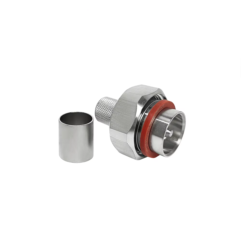
In a modern cellular base station RF transmission path, choosing a heavy-duty coaxial interface involves far more than matching physical thread sizes. A high-performance 7/16 DIN connector must maintain a precise 50-ohm impedance, handle peak continuous RF power, suppress destructive Passive Intermodulation (PIM), and deliver weather-tight seals over decades of outdoor exposure. When custom manufacturing custom components, engineering the interface, cable junction, plating materials, and testing protocols as a single unit is essential for reliable long-term site performance.
Field engineers working around cellular tower feeders know that a connector looking flawless on a CAD drawing can still fail in the field. Poor mechanical torque, improper cable trimming, or sub-standard plating can quickly eliminate performance margins. Evaluating an ODM 7/16 DIN connector requires looking at total assembly performance rather than considering it a generic commodity item.
Core Reasons Base Station Networks Rely on the 7/16 DIN Interface
The 7/16 DIN interface designation refers to its physical dimensions: an inner conductor measuring roughly 7 mm and an outer conductor measuring 16 mm. Standardized under the IEC 61169-4 specification, this robust 50-ohm interface is designed for high-power telecom infrastructure. Its heavy mechanical geometry, deep-threaded coupling mechanism, and large surface contact areas make it ideal for Macro Cell towers, Distributed Antenna Systems (DAS), and remote radio heads where smaller interfaces like N-Type or SMA lack power handling and structural stability.
Power capacity for a 7 16 RF connector is not a static number on a marketing datasheet. While specialized product literature might quote power handling up to 3 kW at 1 GHz, practical operational limits depend heavily on signal frequency, ambient temperature, cable diameter, duty cycle, and altitude. Custom design projects must establish specific power ratings under real-world operating conditions to ensure adequate thermal overhead.
Technical Elements Defining High-Power OEM Connector Engineering
Controlled Impedance Transitions for RF Transmission
High-power performance starts with minimizing internal reflections. The center pin, internal dielectric support, and rear cable transition must form a continuous 50-ohm path through the entire connector body. Any internal physical mismatch causes local signal reflection, increasing Return Loss and creating dangerous thermal hotspots under continuous high-power transmission.
Low-PIM Contact Engineering and Surface Finish Control
Cellular uplinks are vulnerable to Passive Intermodulation generated by subtle nonlinearities at metal-to-metal contacts. While threaded coupling provides stable contact pressure, controlling PIM requires strict manufacturing controls. Plating purity (such as silver or tri-metal alloys), low surface roughness, clean internal threads, and exact center contact retention are critical. Custom specifications should demand verified PIM testing limits (typically -160 dBc or better using two 20W tones) rather than accepting vague low-PIM claims.
Thermal Management and Current Handling Capacities
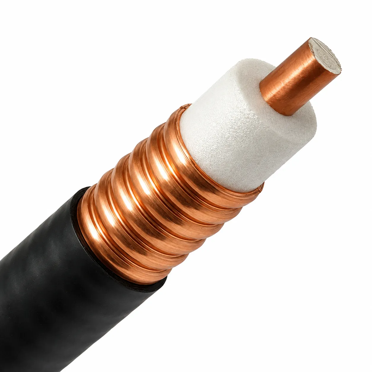
RF current travels along the outer surface skin of conductors. When high power meets micro-resistance at an interface, thermal buildup occurs rapidly. Properly engineered ODM 7/16 DIN connector models feature high-conductivity copper alloy bodies and thick silver-plated spring contacts. Matching the connector body geometry precisely to the corrugated or smooth-wall feeder cable ensures uniform current distribution and prevents heat damage to internal dielectric materials.
Mechanical Retention and Environmental Protection
Outdoor base stations face extreme conditions, including wind vibration, thermal expansion cycles, ice loading, and heavy humidity. Deep threaded coupling provides strong mechanical retention against cable tension, but the rear cable clamp and elastomeric boots must seal the cable jacket properly. Applying secondary weatherproofing tape over an improperly sealed connector housing is never a substitute for a factory-engineered IP68 water-tight seal.
Key Performance Indicators for High-Power Coaxial Interfaces
| Performance Characteristic | Technical Baseline | Field Operational Risk |
|---|---|---|
| Impedance Continuity | 50 Ohm () | Reflected energy causing internal heating |
| PIM Rating | () | Receiver desensitization, dropped calls |
| Coupling Torque | () | Intermittent contact, water ingress |
| Ingress Rating | IP68 (Mated condition) | Moisture ingress, rapid center contact corrosion |
| Mating Cycles | Plating wear-through, elevated contact resistance |
Technical Information Required Before Commencing Custom Manufacturing
Procurement teams frequently specify only the interface name in purchase requests, leading to integration issues. A comprehensive ODM 7/16 DIN connector specification should clearly outline all physical and electrical parameters before starting production runs:
-
Exact gender and mounting format (straight plug, right-angle plug, panel jack, or bulkhead adapter).
-
Mating coaxial cable model, dielectric type, outer conductor diameter, and precise stripping tolerances.
-
Target frequency band, maximum allowable VSWR (Return Loss), and Insertion Loss limits.
-
Peak power handling targets with clear frequency, temperature, and duty cycle parameters defined.
-
PIM performance limits along with the specific test tone powers required during factory testing.
-
Environmental exposure specs including operational temperature range, salt spray resistance, and IP rating.
-
Mechanical constraints covering coupling nut torque limits, cable retention strength, and rear boot geometry.
-
Quality assurance documentation required, such as batch sweep test reports or material compliance certificates.
Clearly defining these parameters prevents receiving a finished 7 16 RF connector batch with mismatched genders, incompatible cable entries, or insufficient plating thickness.
Factory Verification Standards for Base Station RF Assemblies
Evaluating a custom 7/16 DIN connector prior to site deployment requires a structured validation process:
-
Validate the operating environment by mapping frequency range, continuous RF power, cable type, and local climate data.
-
Inspect internal physical construction to verify how center pins, dielectric insulators, and rear clamps integrate with the chosen cable.
-
Require electrical test evidence covering VSWR, Insertion Loss, and PIM testing across the intended frequency band.
-
Confirm installation practices by verifying proper torque wrench settings, strip lengths, and weatherproofing procedures.
-
Implement pre-shipment lot verification by requesting individual sweep test records for completed factory assemblies rather than relying on basic family datasheets.
When to Specify the 7/16 DIN Coaxial Interface
Selecting an ODM 7/16 DIN connector is ideal for high-power broadcast systems, cellular base station feeders, outdoor DAS heads, and surge arrestor interfaces where maximum power margin and PIM control are essential. While smaller formats like 4.3-10 or N-Type suit compact indoor hardware, the physical strength and thermal capacity of the 7/16 DIN format remain a reliable choice for heavy-duty outdoor infrastructure.
Specifying high-power RF components requires matching cable prep, electrical limits, low-PIM design, environmental seals, and factory test records with actual site demands. Aligning these technical parameters provides manufacturing partners a clear build blueprint and gives installation teams reliable components that perform consistently in the field.
For global telecom projects requiring customized coaxial hardware, WORLDPEAK manufactures precision RF connectors and pre-tested cable assemblies tailored to demanding network specifications. By combining strict quality control, advanced PIM sweep testing, and scalable ODM production services, WORLDPEAK helps telecom operators and system integrators deploy reliable high-power base station connections worldwide.