 EN
EN


LMR-400 Cable: Complete Specs, Uses and Compatibility
When an RF link loses margin, the cable run is often blamed last. In antenna systems, it should be checked early. LMR400 is a 50-ohm, low-loss coaxial cable class used where an ordinary feeder begins to consume too much of the signal between radio and antenna. It is a practical option for Wi-Fi antenna extensions, cellular equipment, satellite terminals, test setups, and outdoor point-to-point links—but only when its size, bend needs, connector interface, and loss budget suit the installation.
As an RF systems engineer, I start with frequency, allowed loss, and routing geometry rather than a cable name. That change matters because a run that looks acceptable at VHF may be the weak point at 2.4 GHz or above. This guide covers the working lmr400 specifications, compares the cable with RG8 and RG213, and shows how to calculate an lmr400 cable loss allowance before ordering an assembly.
What LMR400 is—and what to confirm on the datasheet
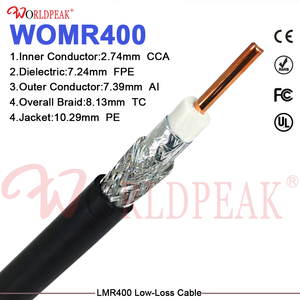
LMR400 refers to a widely used approximately 0.4-inch, 50-ohm, low-loss coaxial format. Common constructions use a center conductor, foamed dielectric, foil and braid shielding, and a weather-resistant outer jacket. That layered construction is intended to reduce attenuation while retaining more installation flexibility than hardline. Exact construction varies by manufacturer and by flexible or ultra-flex version, so treat the family name as a starting point, not as a complete specification.
- Impedance: match 50 ohms across the radio, cable, adapters, and antenna feed.
- Frequency: read attenuation at the operating band, not only at a convenient low-frequency test point.
- Attenuation: use the supplier’s value per unit length for the exact cable and jacket version.
- Mechanical limits: check minimum bend radius, connector termination method, and repeated-flex requirements.
- Environment: confirm jacket suitability for UV exposure, moisture, temperature, abrasion, and indoor plenum requirements where applicable.
A third-party SERP listing quotes 4.25 dB per 100 ft at 1 GHz for one LMR-400 construction. That is useful as an order-of-magnitude check, not a universal promise. The actual lmr400 loss rises with frequency and varies with construction, length, connector count, and installation condition.
Where low-loss coax earns its place
Wi-Fi and remote antenna extensions
For a Wi-Fi access point or bridge with an antenna mounted away from the radio, feeder loss subtracts directly from the benefit of antenna placement. A longer run can still be reasonable when it moves the antenna clear of walls, metalwork, or equipment cabinets. Calculate the trade-off first: the antenna gain and improved line of sight need to exceed the cable and connector loss introduced by the extension.
Cellular, base-station, and distributed RF equipment
Outdoor and rooftop installations usually combine longer routing, exposure, and a need for dependable terminations. Here, LMR400 can be a sound choice for moderate feeder lengths when the cable can be routed without violating bend guidance. Weatherproofing is not an optional finishing step. Moisture ingress at a connector interface can change electrical behavior and create a maintenance issue long after installation.
Satellite and fixed wireless links
Satellite terminals and fixed wireless equipment make frequency-aware planning essential. Higher bands leave less room for casual cable selection. Keep the radio close to the antenna when feasible; otherwise, use the shortest practical run, specify the actual operating frequency in the RFQ, and ask for a tested assembly. For short bench or equipment-rack jumpers that move repeatedly, an ultra-flex alternative may be more appropriate than standard LMR400.
LMR400 vs. RG8 and RG213: a decision framework
| Selection factor | LMR400 | RG8 / RG213 approach |
|---|---|---|
| Attenuation priority | Commonly selected for lower loss in 50-ohm RF feeder applications. | May be acceptable when the run and operating frequency leave adequate link margin. |
| Flexibility | Standard versions are flexible for installation, but diameter still matters in tight paths. | Mechanical feel and flexibility vary by exact cable construction. |
| Outdoor exposure | Choose a jacket and sealing approach appropriate to the site. | Do the same; the cable label alone does not provide weatherproofing. |
| Replacement logic | Often evaluated as an upgrade path from legacy RG8/9913-style feeder runs. | Useful where established cable, routing, and loss requirements already fit. |
There is no universally right option. If the primary constraint is link margin at a higher frequency or a longer run, LMR400 deserves more weight. If repeated bending is the constraint, choose the correct flexible construction and connector strain relief. If cost or routing size dominates, compare the full installed system rather than assuming a nameplate substitution will solve the problem.
How to calculate LMR400 cable loss before you buy
Use the exact cable datasheet and keep units consistent. The basic calculation is:
Total path loss (dB) = cable attenuation (dB per 100 ft or per 100 m) × installed length ÷ reference length + connector and adapter allowance.
- Set the highest operating frequency that matters for the link.
- Find the exact cable attenuation at that frequency.
- Measure the routed length, including service loops, not the straight-line distance.
- Add a realistic allowance for each connector, adapter, lightning protector, or other inline device based on verified component data.
- Compare the result with the system’s available link margin and leave installation headroom.
For example, if a selected cable is specified at 4.25 dB per 100 ft at 1 GHz, a 60 ft run contributes 2.55 dB before connector allowances. The arithmetic is simple; the decision is not. At another frequency or with another construction, that number changes. This is why an lmr400 cable loss estimate should be documented with the exact datasheet revision and the assumed installed length.
Connector compatibility and pre-terminated jumpers
LMR400 describes cable size and impedance, not a single connector. The mating interface must match the equipment port and antenna interface, including gender and any polarity variant. Common 50-ohm interface families used in RF systems include N-type, SMA, TNC, and BNC; whether any one of them is suitable depends on the operating frequency, power, environmental sealing, and the actual port on each end.
For integrators who want to reduce field termination variability, a pre-terminated cable assembly is often easier to control than a bulk cable plus improvised terminations. Worldpeak’s LMR400 Low-Loss 50 Ohm Coaxial Cable is the confirmed product reference for this article. When requesting a jumper, provide cable length, connector family, plug/jack and gender at each end, operating band, installation environment, and whether you need sweep-test documentation.
One practical correction: a connector that mechanically mates is not automatically the right RF assembly. Verify impedance, frequency rating, attachment method for the cable diameter, and weather sealing as a complete set. Then protect outdoor junctions using the approved installation practice for the site.
Final selection checklist
- Confirm 50-ohm system compatibility end to end.
- Budget lmr400 loss at the highest relevant frequency and actual routed length.
- Choose standard or higher-flex construction based on bend and service needs.
- Specify connector interface, gender, polarity, and environmental protection in the RFQ.
- Ask for a pre-terminated assembly when repeatable termination quality and installation speed matter.
- Retain headroom for connectors, adapters, and aging rather than budgeting only the cable.
LMR400 is most valuable when its low-loss capability is treated as part of an RF path, not as a stand-alone product claim. Start with the loss budget, validate the exact cable data, and make connector and environmental choices that preserve the margin you calculated.




