 EN
EN

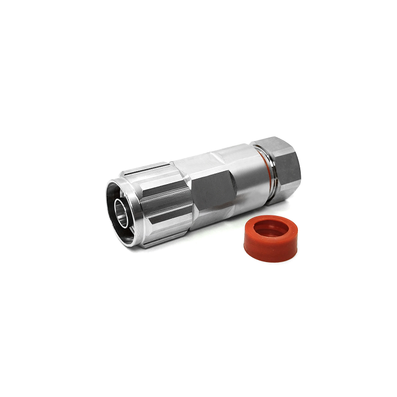
How ODM Coaxial Jumper Supports Unique Test Equipment Layout Needs
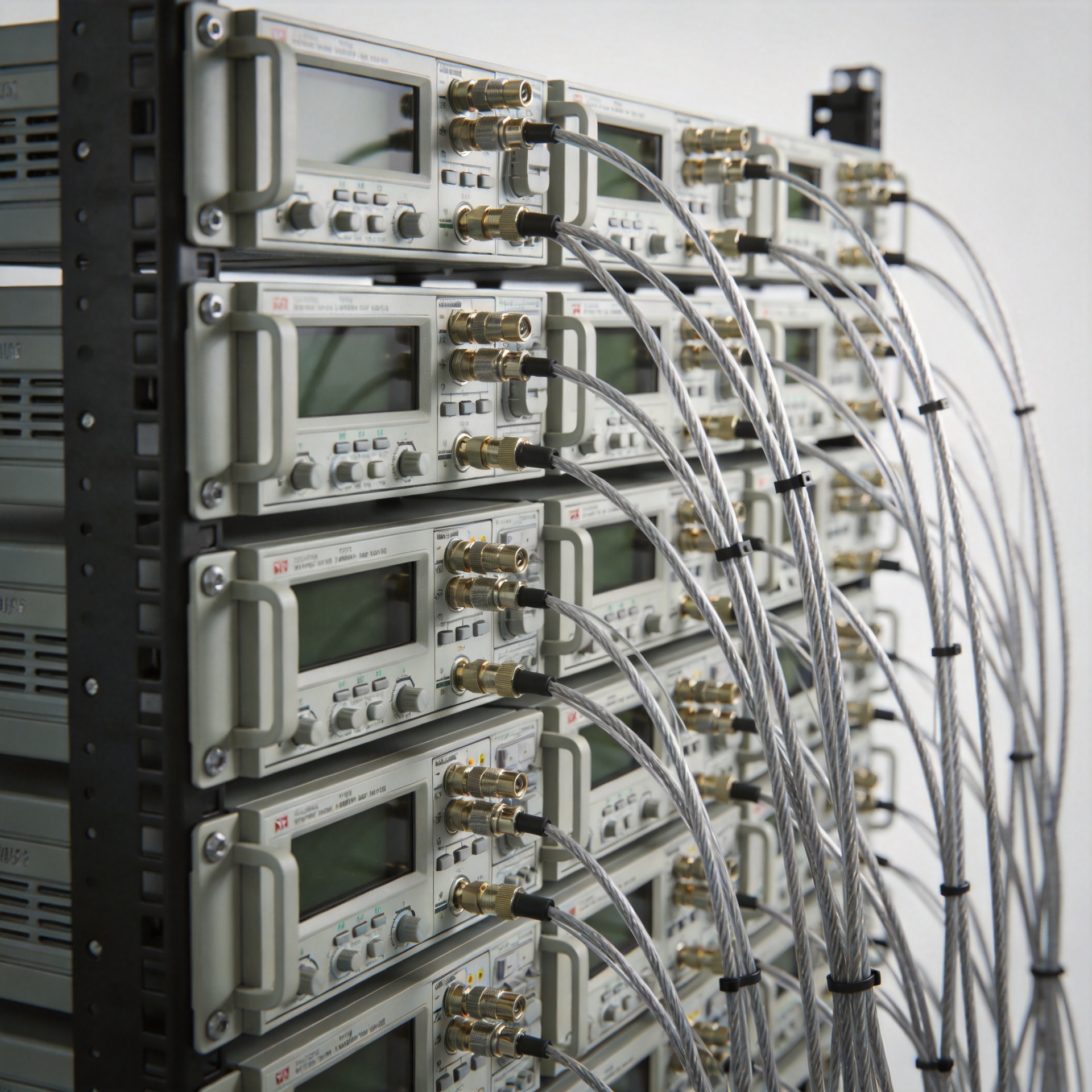
Test equipment setups place demands on RF interconnects that standard catalog assemblies were not designed to meet. Working inside a dense instrument rack, where a signal analyzer sits alongside a vector network analyzer and a calibrated power source, the routing constraints quickly expose the limits of off-the-shelf coaxial jumper options. Standard lengths are often too long, creating excess cable loops that compromise signal path integrity, or too short to reach non-adjacent chassis ports. Connector type combinations rarely align with the mixed-interface reality of heterogeneous test benches.
The mismatch matters practically. In precision RF measurement work, cable routing quality directly influences measurement repeatability. A cable bent below its minimum bend radius degrades VSWR and increases insertion loss in ways that register as measurement error rather than cable failure. A cable that is too long creates mechanical stress concentration points where loops are forced into tight spaces. Understanding how an ODM-supplied coaxial jumper resolves these constraints helps procurement engineers and lab managers specify the right coaxial jumper the first time.
Why Standard Coaxial Jumper Options Fall Short in Test Environments
Standard catalog coaxial jumper assemblies are designed around the most common use cases: fixed-length segments for telecom base station racks, antenna feeder connections, and broadcast infrastructure. Those applications are relatively forgiving about exact routing: a few extra centimeters of cable causes no measurable harm and is easily managed with simple cable ties.
Test equipment racks operate under different constraints. When one device uses an SMA port, the calibration reference has an N-type input, and an older legacy instrument uses a BNC connector, no standard catalog coaxial jumper solves that interconnection problem in one assembly. The engineer ends up using two or three standard assemblies plus an inline adapter, adding connector interfaces to the signal path and introducing potential sources of mismatch.
Bend radius is the other recurring problem. High-density 1U and 2U instrument chassis often have rear-panel ports within 30–40 mm of the rack uprights. A flexible coaxial jumper that must exit the chassis horizontally and then route vertically to another port has almost no room to execute that 90-degree change of direction without being stressed below its rated minimum bend radius. Standard semi-rigid options are geometrically incompatible with these spaces.
Three Non-Standard Requirements That Drive ODM Coaxial Jumper Specification
When instrument rack layouts are reviewed carefully, three recurring requirements emerge that standard inventory cannot satisfy without compromise:
- Custom length: Rack signal paths often require specific cable lengths, sometimes to within ±5 mm, to avoid both mechanical over-tension and excess loop routing. A 230 mm custom-length coaxial jumper with SMA-to-N-type connectors is not a standard catalog item, but it may be exactly what one rack configuration requires. ODM fabrication produces assemblies to user-specified lengths, eliminating the service loops and strain points that catalog alternatives force onto the user.
- Non-standard connector combinations: A flexible coaxial jumper with SMA male on one end and BNC female on the other serves a real need in mixed-interface test racks, yet this combination may not appear in any distributor's standard inventory. ODM capability means the connector combination follows the application requirement, not catalog availability constraints.
- Minimum bend radius compatibility: Test equipment cables routed in tight rack spaces need cable constructions with smaller minimum bend radii than typical telecom coaxial jumper options. Low-flex, high-flexibility cable designs with armored outer conductors or specialized dielectric constructions can achieve operating bend radii that allow routing into physically constrained chassis exit points without performance degradation. High-performance test cables can achieve minimum bend radii as tight as 0.75 inches, enabling cable management that standard catalog assemblies cannot support.
Each of these requirements, taken individually, might be worked around with adapters and creative routing. Together, they describe a situation where the only clean solution is a coaxial jumper designed to specification.
ODM vs. Standard Coaxial Jumper: A Direct Comparison
The practical difference between a standard catalog coaxial jumper and an ODM-specified custom assembly is most visible in three areas:
| Evaluation Criterion | Standard Catalog Coaxial Jumper | ODM Custom Coaxial Jumper |
|---|---|---|
| Length accuracy | Fixed standard lengths; tolerances typically ±10 mm or larger | User-specified length; fabricated to application tolerance |
| Connector configuration | Limited to stocked combinations | Any combination within supported interface families (SMA, N, BNC, TNC, others) |
| Bend radius compatibility | Designed for standard telecom routing; minimum bend radius may exceed rack clearance | Cable construction selected to match minimum bend radius requirement |
| Signal path interfaces | Potential for adapter additions to bridge connector mismatch | Direct interface matching eliminates adapter insertion loss |
| Rack cable management | Excess length requires management loops; potential stress concentration | Exact-length routing eliminates excess cable |
The insertion loss difference from eliminating one inline adapter can be modest (typically 0.2–0.5 dB at microwave frequencies), but in a calibrated test environment, that margin matters. More significantly, each mated interface adds a potential source of VSWR contribution that accumulates across a multi-device test chain.
How an ODM Supplier Supports the Custom Coaxial Jumper Process
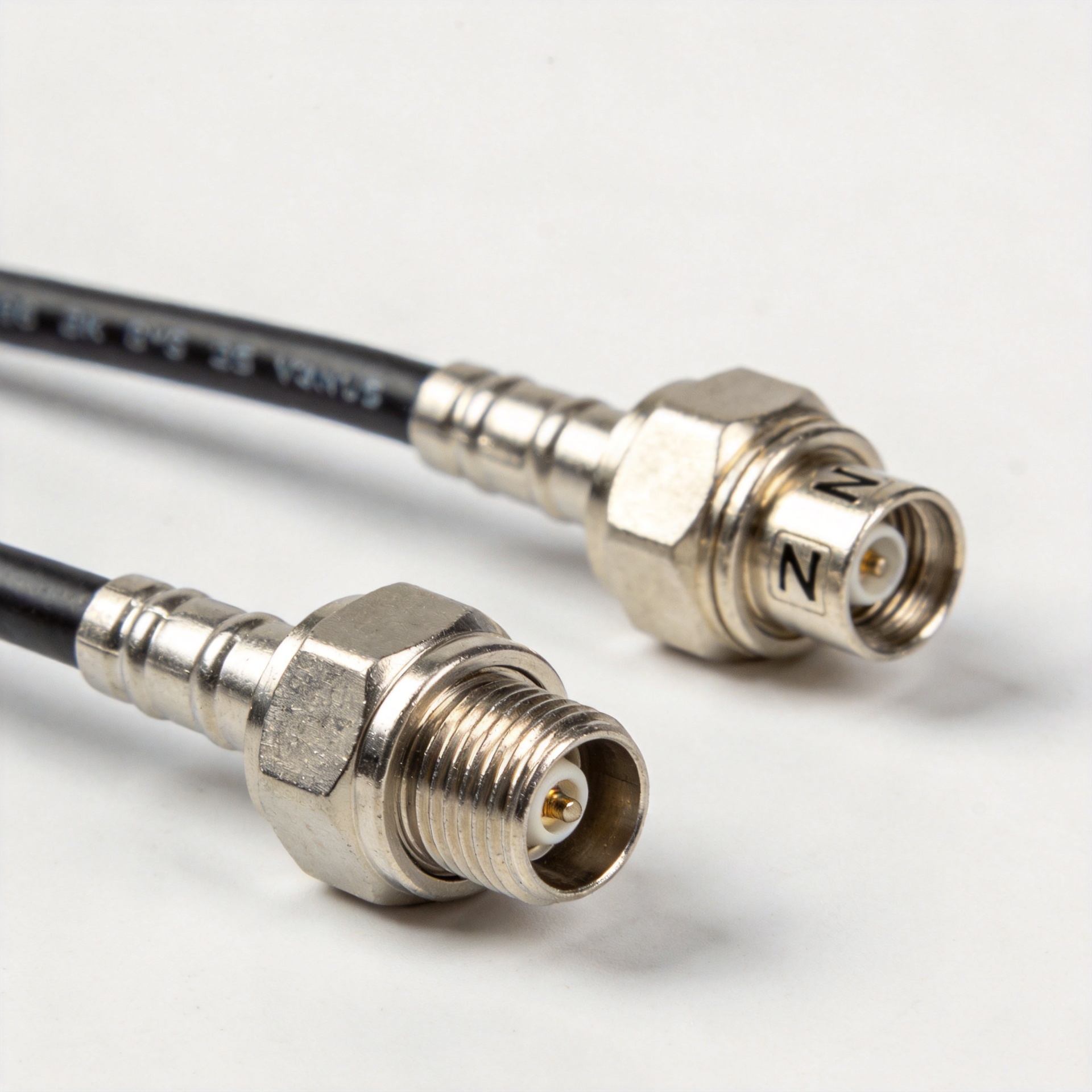
Specifying a custom ODM coaxial jumper for test equipment begins with three inputs: the required connector interfaces at each end, the target routed length in the installed configuration, and the minimum bend radius the routing path requires. A capable ODM supplier translates those inputs into a cable and connector selection, then fabricates and tests each assembly before shipment.
Worldpeak supports this process with cable assembly fabrication capability across SMA, N-type, BNC, TNC, MMCX, SMP, MCX, and 7/16 DIN interface families. Custom length assemblies are produced to user specification, and pre-shipment electrical testing (including insertion loss and VSWR sweep) provides each assembly's performance data before it reaches the test rack. For system engineers who need incoming inspection documentation without performing their own characterization, that pre-shipment test data shortens the validation cycle.
Small-batch ODM orders for custom coaxial jumper sets are also supported, which is significant for laboratory procurement: a test system integration project may need only 8–12 custom jumpers at a time. Minimum order quantities that make sense for production-volume procurement are often impractical for lab procurement, and small-batch capability serves those use cases effectively.
Typical Test Equipment Cases Where ODM Coaxial Jumpers Provide Value
Several test equipment scenarios consistently benefit from ODM coaxial jumper specification:
- Automated test equipment (ATE) racks: ATE chassis require precise RF routing between the test controller and the device-under-test fixtures. Custom lengths and exact connector combinations eliminate the signal path uncertainty introduced by adapters and uncontrolled excess cable in each coaxial jumper segment.
- Multi-port VNA calibration setups: When calibrating a multi-port vector network analyzer, matched-length coaxial jumper assemblies improve measurement confidence. A custom-length ODM coaxial jumper set fabricated to consistent specifications reduces length-induced phase spread across ports.
- Mixed-interface laboratory benches: A bench combining instruments from different generations, each with different legacy connector standards, creates a natural market for custom flexible coaxial jumper assemblies bridging interface families that no standard catalog serves efficiently.
- Rack-mounted signal conditioning systems: Signal conditioning racks with tight rear-panel clearances frequently require cable constructions with smaller minimum bend radii than standard catalog coaxial jumper assemblies support. ODM specification of the cable construction and outer jacket addresses this directly.
Starting the Specification Conversation
The practical starting point for specifying an ODM coaxial jumper is a routing diagram or a simple list: connector type at each end, target length (or acceptable range), any bend radius constraints, and the frequency range the assembly will carry. From that input, a supplier with full interface family coverage and custom fabrication capability can propose a cable and connector combination, confirm the electrical fit with pre-shipment test data, and deliver assemblies that install without routing compromise.
For test engineers who have worked around catalog limitations long enough, cutting cable loops, adding adapters, and noting unexplained measurement variance, the switch to ODM-specified coaxial jumper assemblies often eliminates several sources of test uncertainty in a single procurement decision.





