 EN
EN

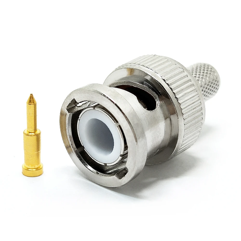
Selecting lmr 400 connectors involves much more than finding an RF port that threads smoothly onto an antenna or radio interface. For rooftop Wi-Fi extensions, cellular base station jumpers, and satellite communication runs, matching the connector body to the actual physical construction of the coaxial cable dictates signal loss, weather resistance, and mechanical stability.
A mismatch between the rear connector ferrule and the outer jacket construction leads to bad shield grounding, loose center contacts, or moisture ingress right where signal integrity matters most.
Starting with Cable Construction Before Choosing Interfaces
LMR 400 serves as a standard 50-ohm, low-loss coaxial cable across fixed and semi-fixed wireless installations. While field technicians often evaluate it alongside RG-8 or RG-213 due to similar outer diameters, relying solely on nominal size introduces severe assembly errors.
Before placing orders for lmr 400 cable connectors, procurement teams should verify specific construction details:
-
Standard Solid Conductor: Standard coax uses a solid aluminum center conductor with copper cladding, requiring pin designs built for stiff center wires.
-
Flexible Stranded Variants: Cable designated as lmr 400 uf (ultra-flexible) utilizes a stranded center conductor and a modified outer rubber jacket.
Because the stranded wire in lmr 400 uf compresses differently, a standard connector pin may fail to grip properly, leading to intermittent signal drops. Specifying the exact cable series alongside housing gender and termination style prevents field returns and rework.
Common Interface Families Compatible with LMR 400
When the rear entry ferrule is engineered specifically for 400-series dimensions, several primary connector families provide reliable 50-ohm performance:
-
N-Type Interfaces: The primary choice for outdoor cellular hardware, wireless access points, and antenna feeds due to its weatherproof threaded coupling.
-
TNC and RP-TNC Interfaces: Threaded compact options ideal for installations exposed to mechanical vibration or space constraints.
-
SMA and RP-SMA Connectors: Widely used on indoor wireless routers and compact radio gear; always double-check center pin polarity before ordering.
-
7/16 DIN Configurations: Specified for high-power broadcast sites and base station jumpers where low passive intermodulation (PIM) is mandatory.
Compatibility relies on two distinct elements: the front mating head must match the equipment port, and the rear termination ferrule must fit the exact outer jacket and dielectric profile.
Comparing Termination Methods: Crimp, Clamp, and Factory Assemblies
Crimp Style Termination
Crimp-style lmr 400 cable connectors deliver fast, highly repeatable assembly in field deployments. Achieving a weather-tight connection requires precise stripping dimensions, correct braid trimming, and a dedicated lmr 400 crimp tool equipped with hex dies calibrated for 400-size ferrules. Using a generic crimper deforms the outer ferrule unevenly, degrading shield braid contact.
Clamp and Solder Options
Clamp-style connectors allow field serviceability without specialized crimping equipment. However, pin soldering demands careful thermal control. Overheating the center pin melts the internal foam dielectric, altering the characteristic 50-ohm impedance and causing signal reflection.
Factory Pre-Terminated Cable Assemblies
For projects lacking calibrated stripping tools or experienced field crews, factory-assembled jumpers remove installation variables. Pre-terminated runs undergo rigorous return loss testing and weather sealing before shipment, guaranteeing performance straight out of the box.
Building a Realistic Signal Loss Budget
Accurate loss calculations require factoring in every component along the transmission path rather than focusing entirely on cable attenuation ratings.
Start by multiplying total cable length by published attenuation figures at target operating frequencies. Then, add a conservative loss margin for every inline connector pair, surge protector, and adapter junction:
-
Cable Attenuation: Standard 400-series coaxial cable exhibits approximately 3.9 dB of signal loss per 100 feet at 1 GHz.
-
Connector and Adapter Loss: Quality lmr 400 connectors introduce roughly 0.1 dB to 0.2 dB of insertion loss per pair when torqued correctly.
-
Impedance Mismatches: Poorly installed connectors create impedance spikes that reflect signal energy back toward the transmitter, inflating total path loss.
Minimizing unnecessary adapter transitions preserves precious signal margin across long antenna runs.
Best Practices for Field Installation and Tooling
-
Verify Cable Designation: Confirm whether the spool is standard solid-core or flexible lmr 400 uf before trimming dielectric layers.
-
Utilize Purpose-Built Tooling: Always use a calibrated lmr 400 crimp tool with matching hex dies to ensure uniform 360-degree ferrule compression.
-
Inspect Center Pin Depth: Check that the center pin sits flush with the dielectric face before crimping outer ferrules to prevent contact damage during mating.
-
Apply Weatherproofing Seals: Outdoor terminations require self-amalgamating silicone tape or cold-shrink tubing over exposed metal housings to prevent moisture ingress.
Key Procurement Questions to Resolve Before Ordering
Can one connector style fit every 400-series cable?
No. Hardware designed for solid center conductors will not seat reliably on flexible lmr 400 uf stranded wires. Always specify the exact cable manufacturer and suffix when ordering lmr 400 cable connectors.
How does proper crimp tooling impact connection lifespan?
Using an approved lmr 400 crimp tool ensures consistent compression around the outer shield braid. Improper tooling causes loose ferrule contact, leading to elevated return loss, moisture leakage, and mechanical pull-out under wind load.
What should a receiving quality check include?
Inspect incoming shipments for correct outer thread gender, pin plating quality, and ferrule dimensions. Visual checks should verify clean center contact alignment, while continuous RF testing confirms reflection limits across operational frequencies.
Streamlining RF Infrastructure with Precision Manufacturing
Deploying reliable wireless infrastructure requires sourcing coaxial hardware from partners who maintain strict machining tolerances, high-grade plating, and dependable supply chains. Inconsistent ferrule sizing or inferior pin materials lead to signal reflection and costly field troubleshooting.
Worldpeak provides engineered RF interconnects, bulk coaxial cables, specialized adapters, and custom pre-terminated cable assemblies for telecom, industrial wireless, and defense applications worldwide. Supported by automated manufacturing infrastructure and strict quality control protocols, Worldpeak delivers robust 50-ohm solutions designed for demanding field deployments.
Whether your next build demands bulk lmr 400 connectors, specialized hardware for lmr 400 uf flexible lines, or custom jumper assemblies, Worldpeak offers factory-direct supply programs tailored to keep project schedules on track.
Frequently Asked Questions
What is the main difference between standard LMR 400 and LMR 400 UF?
Standard LMR 400 features a solid aluminum center conductor suited for fixed building runs, whereas lmr 400 uf utilizes a stranded copper center conductor and a flexible rubber outer jacket designed for applications requiring repeated bending.
Why is a dedicated crimp tool required for 400-series connectors?
400-series cable ferrules require specific hex die sizes to compress the outer shield braid securely without crushing the underlying foam dielectric. A standard or generic tool leads to loose connections or impedance deformation.
Can LMR 400 connectors be reused after field installation?
Crimp-style connectors are single-use components because the ferrule deforms permanently during installation. Clamp-style variants can be reassembled with new gaskets, but factory crimped options provide superior long-term weather sealing.





