 EN
EN

7/16 DIN Connector Guide: High-Power RF Standard
2026/09/24
Choose a 7 16 connector for high-power RF: compare DIN and Type N, protect PIM margin, and apply field installation checks.
2026/09/10
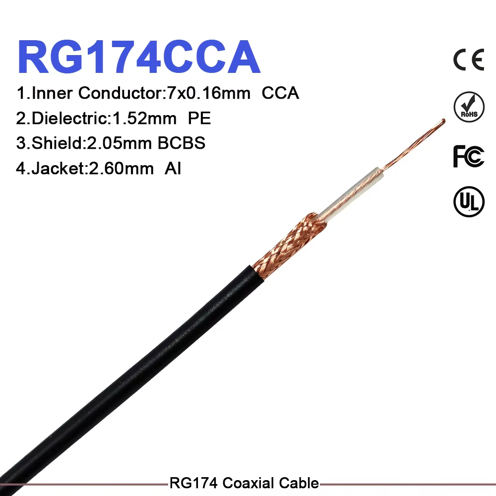
When internal mechanical layout demands minimal component footprint and tight bending radiuses, choosing the right transmission line becomes a critical design step. Compact wireless hardware, handheld testing gear, and IoT sensors frequently require flexible interconnects that operate smoothly without straining fragile solder pads or crowding enclosure volume. Among thin coaxial cables, the classic RG-174 coaxial cable serves as a primary solution for short, space-constrained radio frequency paths.
Featuring a slim profile, fine stranded inner core, and remarkable bending flexibility, this thin coax cable provides an ideal compromise between mechanical versatility and RF efficiency. Understanding its electrical profile, physical trade-offs, connector terminating methods, and installation limits allows hardware engineers to design cleaner internal architectures while maintaining stable signal integrity.
Evaluating the physical dimensions and materials of an RF line helps predict its behavior inside compact enclosures and under thermal or mechanical stress. The rg 174 coaxial cable features a multi-strand center conductor surrounded by solid polyethylene insulation and tinned copper braiding.
| Technical Parameter | Specification Value | Design Impact & Field Notes |
|---|---|---|
| Nominal Outer Diameter | 2.50 mm (0.110 inches) | Compact footprint allows high-density routing |
| Center Conductor | 7 Strands x 0.16 mm Tinned Copper | High flexibility; resists fatigue from vibration |
| Dielectric Material | Solid Polyethylene (PE) | Provides stable 50-ohm geometry along short runs |
| Shield Braid Coverage | Tinned Copper (~95% Coverage) | Blocks localized EMI inside crowded devices |
| Nominal Capacitance | ~101 pF/m (~30.8 pF/ft) | Standard capacitive load for 50-ohm systems |
| Velocity of Propagation | 66% Nominal | Defines physical length for phase-matched paths |
| Maximum Operating Voltage | 1500 V RMS | Suitable for low-power RF and control signaling |
A closely related variant, the rg 174 u coaxial cable, conforms strictly to military specification frameworks like MIL-C-17. While sharing identical nominal dimensions and impedance targets with standard RG-174, the rg 174 u coaxial cable designation often specifies tighter tolerances for braid weave density, jacket flame retardancy, and dielectric purity to support demanding aerospace or marine applications.
Because attenuation accumulates quickly over long distances in small-diameter conductors, engineers deploy this flexible RF cable primarily for short-distance signal distribution. Specific use cases showcase its mechanical advantages:
In one compact spectrum analyzer redesign, swaping out a stiffer cable for an rg 174 coaxial cable saved several millimeters of internal clearance. This extra space provided enough room to expand the internal battery pack without altering the outer aluminum housing dimensions.
Selecting a thin coax cable requires balancing physical flexibility against signal loss. Comparing the performance metrics of popular small-diameter cables illustrates where each type excels:
| Cable Type | Outer Diameter | Attenuation @ 1 GHz | Minimum Bend Radius | Primary Design Strength |
|---|---|---|---|---|
| RG-174 | 2.50 mm | ~1.5 dB/m | 12 mm | Maximum flexibility & low cost |
| RG-316 | 2.50 mm | ~0.9 dB/m | 12 mm | High thermal rating (PTFE insulator) |
| RG-58 | 5.00 mm | ~0.6 dB/m | 25 mm | Lower attenuation over longer runs |
For signal runs under 0.5 meters, the higher attenuation of an rg 174 coaxial cable adds less than 0.75 dB of insertion loss, an acceptable tradeoff in most low-power wireless devices. However, if an internal path runs near high-temperature components or requires soldering directly to hot PCB surfaces, high-temperature options like RG-316 with PTFE dielectrics should be evaluated to prevent insulation melting.
Terminating small-diameter coaxial cables requires precise tooling and correct hardware sizing to maintain structural integrity and low VSWR:
Maintaining stable signal pathways across thousands of commercial devices requires consistent cable production, precise wire stripping, and strict quality control. Slight variations in braid density or contact crimping pressure introduce batch-to-batch performance discrepancies that complicate device testing.
Worldpeak resolves these critical manufacturing challenges through automated stripping equipment, specialized precision crimping tools, and comprehensive testing standards. Offering a broad catalog of custom rg 174 coaxial cable assemblies, rg 174 u coaxial cable jump leads, and specialized RF adapters, Worldpeak manufactures products using premium brass connector bodies, heavy contact plating, and high-purity conductor materials.

2026/09/24
Choose a 7 16 connector for high-power RF: compare DIN and Type N, protect PIM margin, and apply field installation checks.

2026/09/24
Compare TNC connector types, specs and applications, including RP-TNC, bulkhead options, vibration performance and adapter selection.

2026/09/24
Understand MMCX connector basics, RF limits, and how to choose the right coaxial interface for compact systems.

2026/09/24
Understand RP-SMA connector polarity, mating rules, frequency checks, and OEM termination options for reliable RF builds.

2026/09/24
Choose the right bnc male connector for RF, CCTV and test systems with clear 50Ω vs 75Ω, type and installation guidance.

2026/09/24
Compare LMR400 specs, cable loss, uses, connectors and RG8/RG213 alternatives with a practical RF loss-budget method.