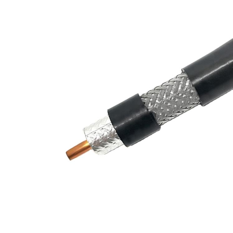
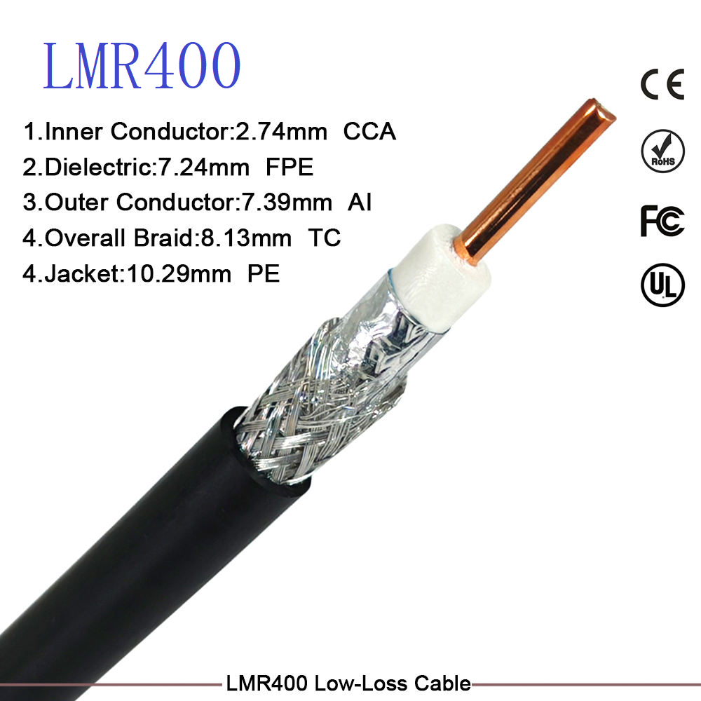
In demanding RF deployments, engineers frequently encounter a frustrating gap: LMR-400 is just too lossy for the required distance or frequency, yet stepping up to LMR-600 introduces excessive weight, stiffness, and cost. LMR-500 was engineered to solve this precise optimization problem. With an outer diameter of 0.500 inches (12.7 mm), it delivers approximately 25% lower attenuation than LMR-400 at 2.4 GHz while maintaining field-installable flexibility that heavier cables simply cannot match. For high-performance 5G, long-haul Wi-Fi backhaul, and high-power broadcast links, LMR-500 represents the optimal balance of electrical performance and mechanical practicality.
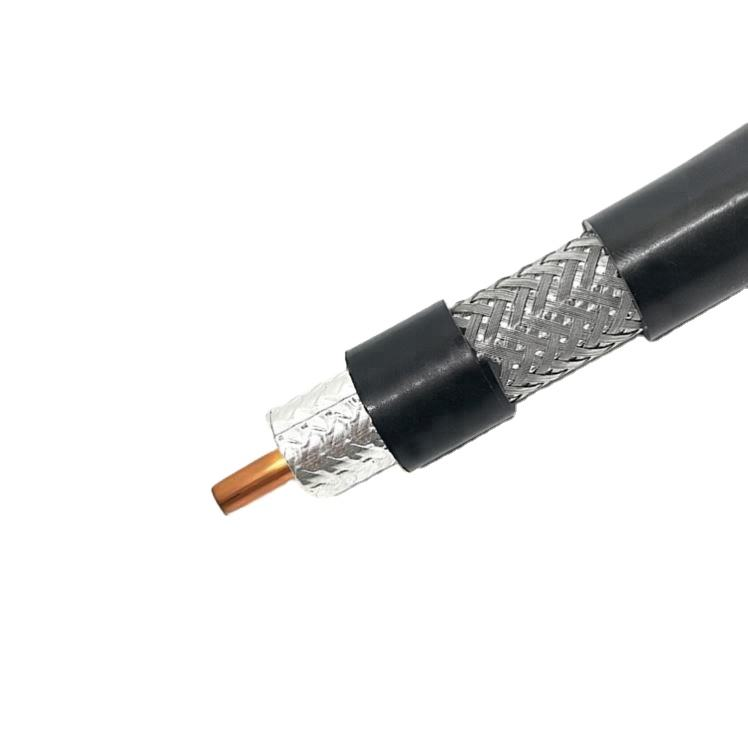
What Is LMR-500?
LMR-500 is a 50-ohm, ultra-low-loss flexible coaxial cable positioned between LMR-400 and LMR-600 in the Times Microwave (Amphenol) product family. It features a large-diameter solid bare copper-clad aluminum (BCC) center conductor, precision foam PE dielectric, and bonded dual-layer shielding. Unlike semi-rigid or corrugated alternatives, LMR-500 retains true flexibility for routing through conduits, around tower structures, and into equipment shelters without specialized bending tools.
Key Technical Advantages
1. Measurably Lower Loss Than LMR-400
At 2.4 GHz, LMR-500 exhibits approximately 5.1 dB/100 ft attenuation versus LMR-400’s 6.8 dB/100 ft—a 25% improvement. At 5.8 GHz, the advantage widens to ~30%. This extra margin translates directly to longer viable link distances, reduced amplifier requirements, or improved SNR at the receiver.
2. Superior Power Handling for High-Wattage Systems
With peak operating voltage exceeding 5,000 Vrms and average power ratings above 1,800W at 1 GHz, LMR-500 safely handles high-power transmitter outputs for FM broadcast, amateur radio EME, and radar systems where LMR-400 would approach thermal limits.
3. Field-Friendly Flexibility at 0.5" OD
Despite its larger size, LMR-500 maintains a repeated bend radius of just 5 inches (127 mm). This is significantly more manageable than LMR-600 (7.5" bend radius) and eliminates the need for pre-formed bends or hydraulic benders required by semi-rigid cables of comparable performance.
4. Bonded Shield Moisture Resistance
Like all genuine LMR-series cables, LMR-500 uses bonded foil construction that prevents longitudinal moisture migration—a critical reliability factor for outdoor aerial and direct-burial installations where traditional non-bonded RG-214 equivalents fail prematurely.
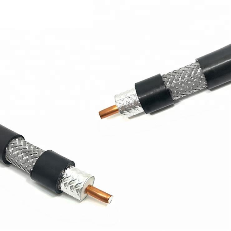
Quick Specifications at a Glance
|
Parameter
|
Specification
|
|
Impedance
|
50 Ω
|
|
Outer Diameter
|
0.500" (12.7 mm)
|
|
Center Conductor
|
Solid BCC, 0.142" (3.61 mm)
|
|
Dielectric
|
Foam PE
|
|
Shielding
|
Bonded Foil + Tinned Copper Braid (>90 dB)
|
|
Frequency Range
|
DC – 6 GHz (usable to 8 GHz)
|
|
Velocity of Propagation
|
85%
|
|
Attenuation @ 900 MHz
|
~3.0 dB/100 ft (9.8 dB/100 m)
|
|
Attenuation @ 2.4 GHz
|
~5.1 dB/100 ft (16.7 dB/100 m)
|
|
Min. Bend Radius (Repeated)
|
5.0" (127 mm)
|
|
Peak Operating Voltage
|
5,000 Vrms
|
Note: Always verify against your supplier’s official datasheet. Specifications may vary between genuine Amphenol/Times Microwave products and third-party equivalents.
Primary Applications
● 5G NR Macro Sites: Extended feeder runs (30–60m) at 3.5 GHz and 4.9 GHz bands where LMR-400 loss exceeds link budget.
● Long-Haul Wi-Fi Backhaul: Point-to-point bridge feeds at 5.x GHz requiring maximum signal margin.
● FM/TV Broadcast Translators: High-power feeder lines for medium-power transmitters and combiner outputs.
● Amateur Radio EME & Contest Stations: Low-loss feeds for large Yagi arrays and high-power amplifiers at 432 MHz and above.
● Military & Defense Radar: Mobile radar antenna feeds requiring both low loss and rapid deployability.
● GPS/GNSS Precision Timing Networks: Campus-wide distribution with minimal delay variation over extended distances.
LMR-500 Positioning in the Full LMR Family
|
Model
|
OD
|
Loss @2.4GHz
|
Bend Radius
|
Max Practical Run @2.4GHz
|
Role
|
|
LMR-240
|
0.280"
|
11.5 dB/100ft
|
2.8"
|
5–15 m
|
Mid-Range Trunk
|
|
LMR-400
|
0.405"
|
6.8 dB/100ft
|
4.0"
|
15–50 m
|
Standard Long-Haul
|
|
LMR-500
|
0.500"
|
5.1 dB/100ft
|
5.0"
|
25–70 m
|
High-Performance Flexible Feeder
|
|
LMR-600
|
0.590"
|
4.3 dB/100ft
|
7.5"
|
50–100 m
|
Extra-Long Haul / Max Power
|
|
RG-214
|
0.425"
|
~9.5 dB/100ft
|
4.0"
|
≤15 m
|
Legacy Dual-Shield (Obsolete)
|
Critical Engineering & Procurement Notes
● Connector Specificity Is Non-Negotiable: LMR-500 requires dedicated LMR-500 connectors. Do not attempt to use LMR-400 or LMR-600 connectors—the center conductor diameter, braid capture geometry, and crimp dimensions are unique. Improper termination causes VSWR degradation, PIM issues, and potential arcing under high power.
● Availability & Lead Time Considerations: LMR-500 is less commonly stocked than LMR-400 or LMR-600. For project-critical deployments, confirm inventory and lead times early. Some distributors offer certified equivalents (e.g., Pasternack PE-C500, MPD LMR-500-EQ) with matching specifications when genuine Amphenol stock is unavailable.
● Weight & Support Spacing: At ~0.14 lb/ft (0.21 kg/m), LMR-500 is noticeably heavier than LMR-400. Ensure cable hangers, clips, and conduit supports are rated for the increased weight, especially in vertical tower runs. Follow manufacturer-recommended support spacing (typically every 2–3 feet vertically).
● PIM-Sensitive Deployments: For multi-carrier 5G DAS or sites requiring PIM < -155 dBc, specify Low-PIM LMR-500 variants. Standard LMR-500 is adequate for single-carrier Wi-Fi, amateur radio, and non-critical broadcast links.
● Cost-Benefit Validation: Before specifying LMR-500, run a full link budget comparing it against LMR-400 + inline amplifier vs. LMR-600. In many cases, the total installed cost (cable + connectors + labor) of LMR-500 is lower than LMR-600 while outperforming amplified LMR-400 solutions in reliability and noise figure.
Conclusion
LMR-500 exists for engineers who refuse to compromise. When LMR-400 falls short on loss or power, and LMR-600 exceeds mechanical or budgetary constraints, LMR-500 delivers precisely calibrated performance without excess. Its combination of sub-6 GHz ultra-low attenuation, high power handling, and genuine field flexibility makes it an indispensable tool for next-generation wireless infrastructure. While less ubiquitous than its 400 and 600 siblings, LMR-500 remains the definitive solution for projects where every dB and every installation hour counts.
Evaluating LMR-500 for your next deployment? [Request a Custom Quote] for bulk cable and matched connectors, or [Consult Our RF Engineers] for link budget validation and alternative analysis. We help you select the right cable—not just the biggest one.
 EN