 EN
EN

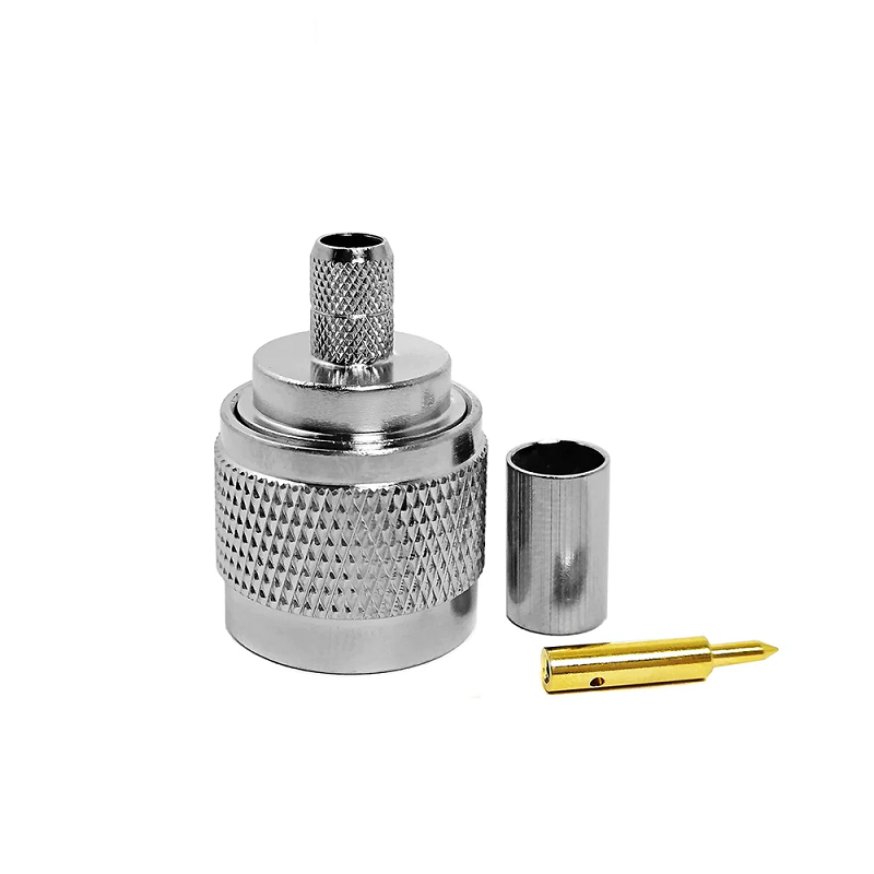
In high-performance radio frequency distribution systems, cellular base stations, and ruggedized outdoor antenna networks, the n female connector serves as the primary boundary interface between external transmission cables and internal sensitive electronic modules. Operating as a medium-sized, threaded coupling interface, the Type N connector is valued for its mechanical robustness and continuous coaxial shielding. However, selecting a panel-mount or bulkhead receptacle based solely on physical threading often leads to impedance discontinuities, high return loss, and premature environmental sealing failures under field stress.
Achieving repeatable microwave performance requires RF hardware engineers and procurement specialists to carefully evaluate characteristic impedance variations, structural mounting geometries, high-power heat dissipation limits, and environmental ingress protection standards.
Mechanical Benefits of the Threaded Type N Interface on Equipment Panels
The selection of an n female connector for a chassis interface provides substantial physical and electrical advantages over quick-disconnect push-on or bayonet-style alternatives. The standard 5/8-24 UNEF threaded coupling mechanism ensures that once fully mated to a corresponding male plug, the joint remains locked against vibration, thermal expansion, and mechanical cable pulling forces.
-
Threaded coupling provides uniform circumferential clamping force, optimizing outer ground path contact and reducing passive intermodulation.
-
Hand-tightened or torque-wrench-calibrated connections prevent accidental decoupling inside high-vibration environments like railway transceivers or wind turbine monitors.
-
Heavy outer metal shells protect delicate internal contact baskets from direct impact, tool slippage, and rough handling during field servicing.
-
Standardized mechanical configurations support intermateability across global hardware suppliers, streamlining replacement workflows on remote cell towers.
Critical Technical Hazards: 50 Ohm versus 75 Ohm N-Type Interfaces
A primary technical failure mode in mixed broadband networks involves mixing up 50 Ω and 75 Ω characteristic impedance variants of the Type N family. While sharing the identical outer threaded coupling shell, their internal center contact dimensions are radically different.
A 50 Ω n female connector is designed for general telecommunications, defense radar, and laboratory test instruments, utilizing a thicker center female socket basket to support a 50 Ω coaxial line.
Conversely, a 75 Ω n type female connector is optimized for high-definition video distribution networks, digital television headends, and satellite receivers, using a significantly thinner female contact socket.
| Interface Parameter | 50 Ohm N-Type Specification | 75 Ohm N-Type Specification |
|---|---|---|
| Target Applications | Cellular Infrastructure, Radar, Microwaves, Test Instruments | CATV Systems, Satellite Headends, Video Routing |
| Characteristic Impedance | 50 Ω | 75 Ω |
| Center Pin Outer Diameter | Approximately 1.65 mm to 1.68 mm | Approximately 1.00 mm to 1.04 mm |
| Dielectric Configuration | Solid PTFE Support surrounding the Center Socket | Air Dielectric or Minimal Support Ring |
| Maximum Safe Frequency | Up to 11 GHz (Standard) / 18 GHz (Precision) | Up to 1.5 GHz (Standard) / 3 GHz (High-Speed) |
| Mechanical Collision Risk | Mates securely with standard 50 Ω male plugs | Forcing a 50 Ω male pin inside destroys the female contact |
If a standard 50 Ω male pin (diameter ~1.67 mm) is forced into a 75 Ω n connector female socket (designed for a ~1.02 mm pin), the oversized male contact will permanently stretch, crack, or split the delicate female contact fingers. Once physically distorted, the 75 Ω socket cannot return to its original shape, resulting in an open circuit or severe signal reflections when a correct 75 Ω pin is subsequently inserted.
Mechanical Form Factors for Enclosure Packaging
Integrating an n type female port into a shielded enclosure requires choosing a chassis mounting geometry that balances structural shear loads with tight spatial constraints.
Four-hole flange designs incorporate a square or rectangular metal flange with four mounting holes for screws. Secured directly to a flat machined face on the enclosure, the flange distributes cable torque and bending stress across a wide surface area, making it ideal for thick-walled cast aluminum housings.
Bulkhead configurations feature a completely threaded external barrel that passes through a single circular panel cutout, secured from the exterior with a lock washer and a single mounting hex nut. Bulkhead units save critical panel area on high-density RF patch panels and often incorporate a flat D-profile on the barrel. This D-flat registers against a matching D-shaped chassis hole to prevent the connector body from rotating when field technicians apply mating torque.
Right-angle panel receptacles divert internal cable routing by 90 degrees directly behind the panel face. This orientation fits shallow equipment racks where a straight internal connection would protrude too deep, though engineers must account for the slightly higher return loss typically introduced by right-angle internal transition junctions.
Ingress Protection and Weatherproofing for Outdoor Deployments
Outdoor antenna installations, wireless base stations, and marine navigation arrays require continuous protection against rainwater, dust, salt fog, and condensation. Securing an n female connector requires a robust weatherproofing plan rather than relying on threaded coupling alone.
-
Outer silicone or fluorosilicone O-rings positioned inside custom-machined flange grooves compress tightly against the panel exterior to establish a reliable IP68 water-tight seal.
-
Internal epoxy barriers or glass-to-metal hermetic seals prevent gas and moisture from traveling through the dielectric boundary into the dry equipment interior.
-
Panel cutout mounting surfaces must be free of paint, powder coating, and burrs to ensure low RF contact resistance and clean grounding shield continuity.
-
Weatherproofing boots or self-amalgamating silicone tapes wrapped around the mated type n female joint protect threads from ambient corrosive road salt and humidity.
Failure to secure the panel boundary allows moisture to penetrate the coaxial transition. Water ingress degrades the dielectric constant of the internal PTFE support, creating severe impedance dips and causing rapid oxidation of the internal contact surfaces.
RF Performance, Return Loss, and High-Frequency Signal Integrity
At microwave frequencies, physical manufacturing tolerances directly dictate signal reflection parameters. Any microscopic eccentricity between the center conductor and the outer shield cavity, or any air gap in the PTFE dielectric, creates a localized capacitive or inductive spike.
Deploying a precision type n female connector ensures a smooth electromagnetic transition with minimal insertion loss up to 11 GHz, with extended precision components sustaining performance up to 18 GHz.
| Frequency Spectrum | Target Insertion Loss | Target Return Loss | Maximum Recommended VSWR | Typical Applications |
|---|---|---|---|---|
| DC to 3.0 GHz | < 0.05 dB | > 32 dB | < 1.05:1 | LTE/5G Cellular, L-Band GPS, Industrial IoT |
| 3.0 GHz to 6.0 GHz | < 0.10 dB | > 26 dB | < 1.10:1 | Wi-Fi 6E/7 Infrastructure, C-Band Satellites |
| 6.0 GHz to 11.0 GHz | < 0.15 dB | > 20 dB | < 1.22:1 | X-Band Defense Radar, Microwave Backhauls |
| 11.0 GHz to 18.0 GHz | < 0.25 dB | > 15 dB | < 1.43:1 | Ku-Band Satellite Feeds, Lab Calibration Ports |
System verification plans should incorporate Vector Network Analyzer (VNA) sweep testing across the target operating band to record S-parameters, verifying that installed chassis assemblies do not introduce unbudgeted insertion losses.
High-Power Power Handling and Temperature Derating Rules
The power-handling capacity of an n female connector is limited by heat dissipation and voltage breakdown limits. Unlike miniature interfaces, the larger physical mass of the Type N connector supports higher continuous wave (CW) power, but this capacity drops significantly as frequency and temperature rise.
As operational frequencies increase into the microwave region, skin-effect losses concentrate electrical current on the outermost microscopic surface of the center contact pin, generating localized thermal energy. Combined with high ambient temperatures inside unventilated outdoor enclosures, the internal connector junction can easily exceed the thermal degradation threshold of its PTFE dielectric (~165°C).
Designers must apply strict derating curves when routing high-power transmit signals. A connector rated for 1000 Watts CW at 1 GHz may support less than 200 Watts CW when deployed at 10 GHz in an outdoor enclosure exposed to direct summer sunlight. Specifying silver or tri-metal plating over high-conductivity brass bodies optimizes thermal transfer and minimizes contact resistance over extended high-power broadcast cycles.
Assembly Verification and Quality Assurance Protocols
To guarantee long-term electrical reliability in the field, manufacturing and incoming inspection workflows must implement rigorous quality control metrics:
-
Non-contact optical comparator gauging to verify internal contact socket depth and pin diameter against MIL-STD-348 and IEC 61169-16 standards.
-
X-ray fluorescence plating analysis to confirm consistent gold and nickel layer thickness on contact pins, ensuring survival over 500 mating cycles.
-
Mechanical contact retention force testing to confirm the female socket basket maintains uniform radial pressure on mated pins under severe vibrational shock.
-
Neutral salt-spray chambers to test external connector plating against corrosive atmospheric humidity for 48 or 96 hours.
Precision Manufacturing and Supply Chain Solutions with Worldpeak
Deploying reliable RF infrastructure requires consistent physical tolerances and certified electrical parameters across manufacturing runs. As an established RF hardware manufacturer and global exporter, Worldpeak delivers comprehensive custom engineering, rapid prototyping, and volume OEM/ODM supply chain solutions. Utilizing advanced multi-axis CNC Swiss turning centers, Worldpeak achieves machining tolerances down to ±0.005 mm, ensuring that every n female connector exhibits exceptional mechanical concentricity, smooth thread engagement, and stable impedance.





