n-female-to-n-female-lightning-arrester---dc---3-ghz, n-female-to-n-female-lightning-arrester---dc---3-ghz, /rf-lightning-arrester
Inquiry
Inquiry

N Female to N Female Lightning Arrester - DC - 3 GHz

This N Female to N Female lightning arrester is a GDT based RF surge protector designed for DC - 3 GHz operation. It sits in the transmission line between the antenna and the radio equipment, diverting lightning-induced transients to ground before they reach the sensitive front end. The 50 ohm design holds insertion loss at 0.2 dB with a VSWR of 1.25 or better across the passband.

Request a Quote  |  Download Datasheet  |  Ask an Engineer

Request a Quote WhatsApp
  • Overview

Overview

Product Overview

The N Female to N Female lightning arrester is an in-line lightning arrester and RF surge protector for 50 ohm coaxial systems operating from DC to 3 GHz. A 90 V gas discharge tube (GDT) is the protective element. In normal service, the lightning arrester remains a high-impedance part of the line so the RF path continues with a stated insertion loss of 0.2 dB. During a surge, the lightning arrester GDT changes state rapidly and directs the transient toward the grounding connection.

This N Female to N Female lightning arrester combines a low-capacitance lightning arrester protection method with a serviceable discharge element. That approach supports broadband RF use without the signal loading associated with some diode-based solutions. Because a GDT has a higher operating threshold than a diode limiter, the device is best applied where a proper external grounding path is available and antenna-line protection is the priority.


Protection Mechanism and Construction

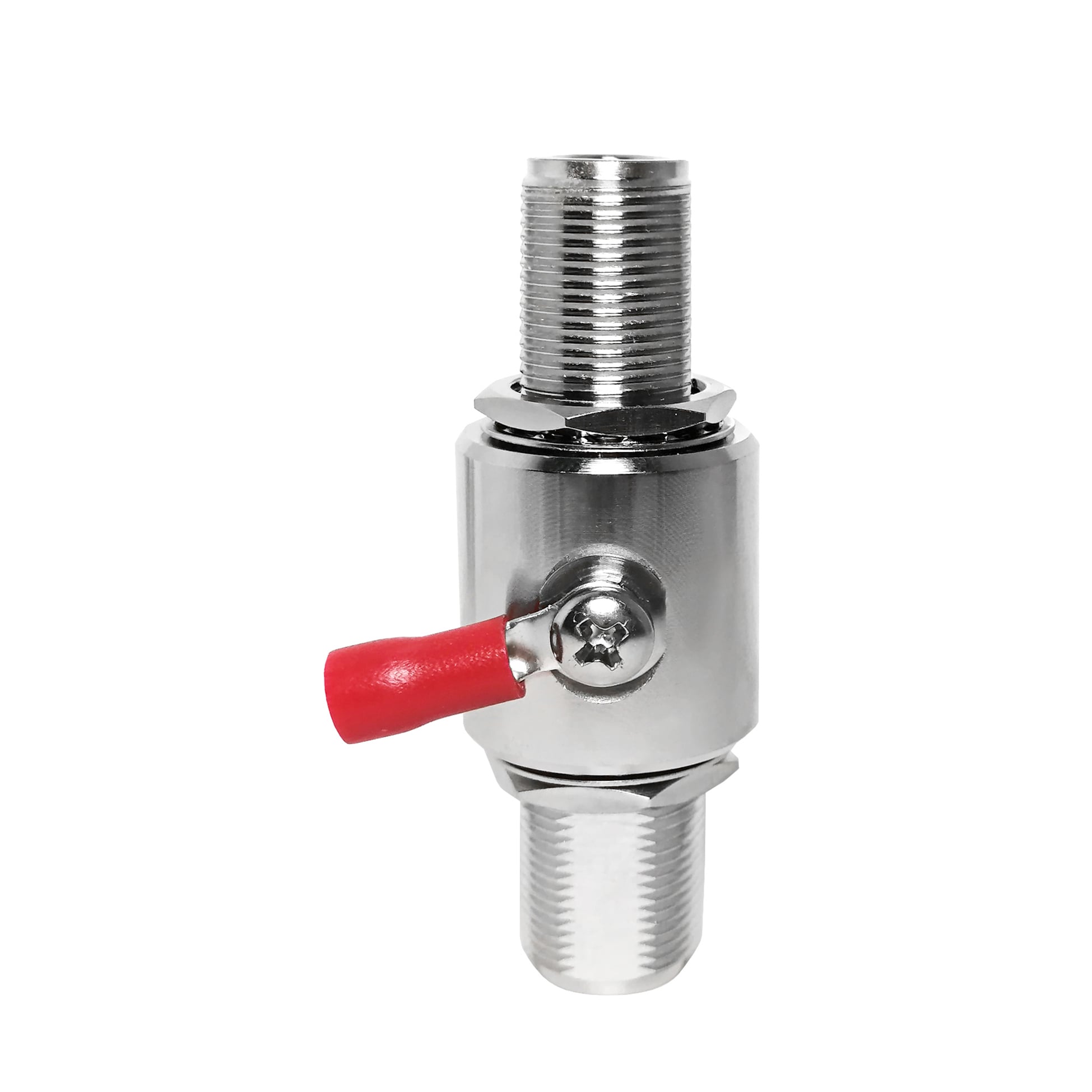
  • Protection Element: This lightning arrester uses a 90 V gas discharge tube with a 10 kA capability on the 8/20 us waveform. It is located in the central lightning arrester assembly and may be accessed for replacement without removing the cable assembly from the N female interfaces.
  • Grounding Path: A side-mounted ring terminal provides the connection from this lightning arrester grounding terminal to the site earth bar. For this lightning arrester, the effectiveness of the installation is closely linked to the inductance and length of this ground connection.
  • Body: The lightning arrester housing is machined brass with corrosion-resistant plating. Its bulkhead-to-bulkhead construction is suited to panel, wall-entry, and enclosure mounting positions.
  • Connector Interface: N Female to N Female connectors allow the lightning arrester to join standard cable assemblies without changing their connector format. Use the torque requirements specified by the applicable connector manufacturer.


Reference Technical Specifications

The following values identify this N Female to N Female lightning arrester configuration.

Parameter

Specification

Notes

Connector Interface

N Female to N Female

Standard RF connector

Mounting Style

Bulkhead to Bulkhead

Body configuration

Impedance

50 ohm

System impedance

Frequency Range

DC - 3 GHz

Passband

Insertion Loss

0.2 dB

Across passband

VSWR

1.25

Maximum

Power Handling

200 W

CW, reference

Discharge Element

90 V

Gas discharge tube

Surge Current

10 kA (8/20 us)

8/20 us waveform

Grounding

Ring terminal

M4 lug, ground wire

Body Material

Machined brass

Corrosion-resistant plating

Weight

128.6 g

Approximate

Typical Application

Panel feed-through, shelter wall entry, patch panel

Primary use case

These lightning arrester reference figures apply to this protection family and should be verified for the selected final configuration.


Engineering Comparison

  • Compared with a quarter-wave stub: A quarter-wave device protects at its designed frequency range and provides a DC-grounded path, but its useful response is comparatively narrow. This RF lightning arrester covers DC to 3 GHz, helping sites that use more than one radio band avoid frequency-specific retuning.
  • Compared with a diode-based protector: Diode limiters can react at a lower threshold, while their capacitance can influence high-frequency performance and power capability. The lightning arrester GDT structure is specified for 0.2 dB insertion loss and 200 W reference power handling.
  • Compared with a DC-block surge protector: A DC block interrupts DC and some low-frequency paths, but it does not replace an earth route for a high-energy transient. This lightning arrester is designed to send surge energy to the grounding system through its dedicated terminal.


Applications

  • Panel feed-throughs, shelter entries, and patch panels: Install this lightning arrester where an antenna feeder crosses into a protected radio space to limit induced surge energy on the coaxial line.
  • Towers and rooftop antenna systems: This lightning arrester body can be positioned at cabinet or shelter entry points, establishing an earth reference for the transmission line when connected to the site grounding arrangement.
  • Multi-band radio locations: The DC - 3 GHz range allows this lightning arrester format to cover legacy and current radio paths within the stated passband.
  • Equipment racks and test installations: Place this lightning arrester near a radio or instrument input to help protect equipment connected through longer external cable runs.


Installation and Grounding Notes

  • Prioritize grounding: Connect the ring terminal to the earth bar with the shortest practical, suitably sized lead.
  • Mounting position: Secure this bulkhead lightning arrester at the cable entry or another position within the protected zone of the lightning-protection arrangement.
  • Connector care and sealing: Tighten the N female connectors according to the connector manufacturer's guidance. For outdoor use, protect the connector interfaces with appropriate weatherproofing tape or a weather boot.


OEM and B2B Support

  • OEM Customization: Connector combinations, 90 V or 230 V discharge options, and special plating can be supplied for volume orders.
  • Cable Assembly Options: Factory-terminated jumper assemblies with the lightning arrester pre-installed can be supplied for plug-and-play installation.
  • Packaging and Marking: Individual protective packaging, custom labeling, and batch test reports are available on request. This lightning arrester can be marked for project identification.


FAQ

Q: When should the gas discharge tube be replaced?

A: The 90 V GDT is rated at 10 kA on the 8/20 us waveform. After a substantial surge, test the tube for leakage and hold-off performance. If it does not pass inspection, replace the tube rather than the complete lightning arrester.


Q: Will this RF lightning arrester affect a DC - 3 GHz signal?

A: The stated insertion loss is 0.2 dB and the maximum VSWR is 1.25 over the passband. These values support use in antenna-line applications where maintaining the RF signal path is important.


Q: Can this lightning arrester be installed indoors?

A: Yes. It may be used at the cable entry point or at the equipment end of a cable run. In either location, the lightning arrester needs an effective earth connection for lightning arrester operation to perform its intended lightning protection function.

Featured Products