 EN
EN

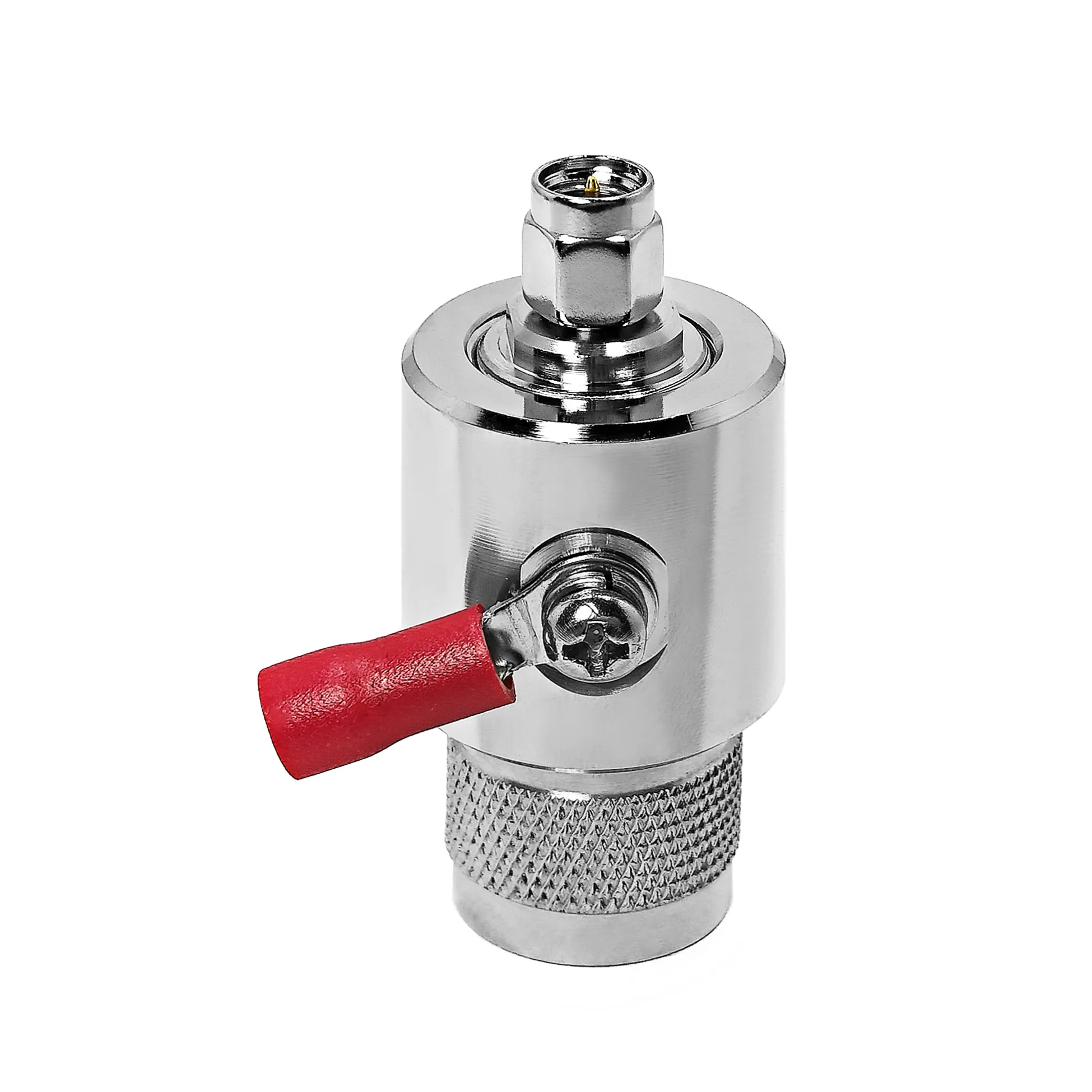
N-Male Connector: Threading Torque and Specs
In microwave and RF work, an n male connector is often selected because its threaded coupling gives an assembly more mechanical security than a quick-connect interface. That advantage is useful only when the entire signal path is specified correctly. As an RF systems engineer, I start with frequency range and impedance, then check cable geometry, environmental sealing, and the connector manufacturer’s assembly drawing. A threaded interface that feels tight is not, by itself, evidence of a low-reflection connection.
The N family remains a familiar 50-ohm interface for antennas, test assemblies, radios, filters, and outdoor feeder runs. Its durable coupling is one reason it appears in installations where vibration, handling, or weather exposure make a lighter connector family less suitable. The practical question is not whether an N interface is “better” in every design. It is whether its mechanical format, electrical rating, and assembly process fit the equipment on both sides of the connection.
What an N Male Connector Actually Mates With
An n male connector normally has the coupling nut and the mating center-contact arrangement required to join an N female jack. The threaded shell provides the retention force; the center contact and dielectric geometry control the RF transition. Because both mechanical and electrical geometry matter, an n connector male should be selected as a complete interface definition: 50-ohm or 75-ohm system convention, cable type, termination method, frequency requirement, and environmental need.
The terms n type male and N male are commonly used for the same gender description, but they do not replace a full part specification. Two parts can both be called N male while differing in crimp dimensions, solder method, panel geometry, plating, sealing parts, or usable frequency. Confirm the manufacturer drawing before approving a cable build or replacement part.
Threading Torque: Treat the Drawing as the Authority
Threaded connectors reward a controlled mating process. Under-tightening can leave the interface vulnerable to loosening, inconsistent grounding, or moisture entry. Over-tightening can damage threads, deform a gasket, or impose unnecessary stress on the cable and equipment jack. There is no responsible universal torque number for every n male connector, because the recommended value depends on the exact connector construction, material, mating condition, and supplier instructions.
For field work, use the connector manufacturer’s specified torque tool or wrench setting where one is supplied. Hold the mating jack so the equipment panel does not take the twisting load, keep the threads clean, and avoid using pliers on the coupling nut. If the installation environment stays wet, dusty, or exposed to daily temperature swings, inspect the seal and strain relief before tightening. Torque cannot correct a nicked cable jacket, a cross-threaded coupling, or a mismatched interface.
Common N-Type Variants
- Cable-mounted male plugs: used on coaxial jumpers and feeder cables; the termination must match the cable diameter and construction.
- Female bulkhead or panel jacks: used when a sealed, repeatable equipment entry point is needed. Check panel thickness, flange pattern, and rear clearance.
- Right-angle versions: useful in tight enclosures, but bend radius and cable routing still affect mechanical life and RF stability.
- Adapters: useful for controlled interface changes, but each transition should be evaluated for its operating band and power conditions.
A high-power interface must be judged from its published rating, not from the size of the coupling nut. For example, the verified product record for the RFX-Custom-02 7/16 DIN Female to N Male RF Connector lists a 0–3.5 GHz range and 3 kW at 2.5 GHz. Those values apply to that identified product, not to every N adapter. Confirm frequency, power, duty cycle, and mating interface for the part you are buying.
N Type vs. TNC and BNC
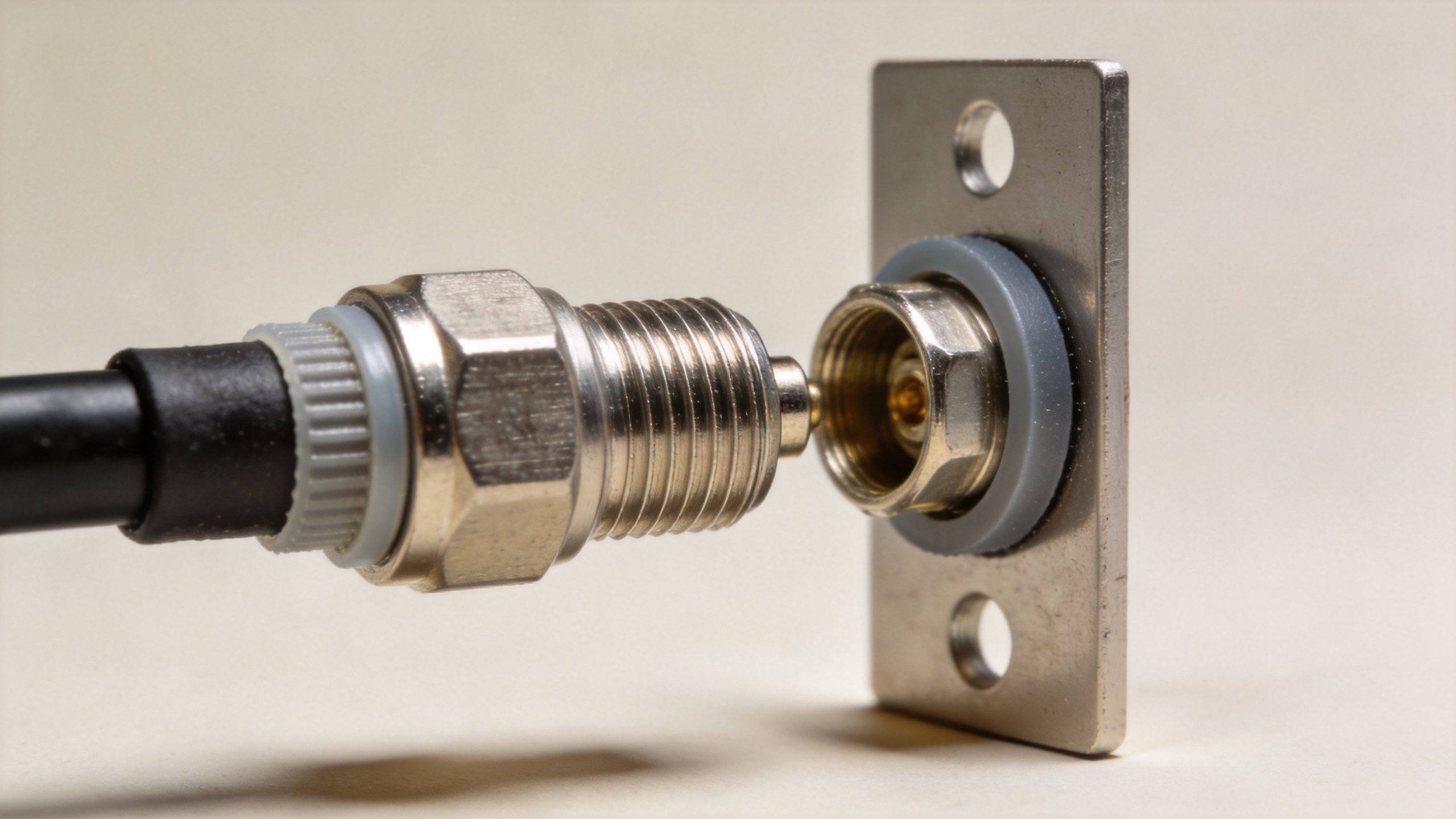
N, TNC, and BNC connectors may all appear in 50-ohm RF assemblies, but they are not mechanically interchangeable. An N interface uses a larger threaded coupling; TNC also threads but uses a smaller form factor; BNC relies on a bayonet coupling. Do not try to mate them directly or assume that an adapter preserves the frequency capability of the highest-rated component. The assembled path is limited by its lowest-rated connector, cable, adapter, and installation condition.
For applications where space is limited and a threaded coupling is still preferred, TNC may be considered after checking its frequency and environmental requirements. BNC is convenient for many laboratory and lower-frequency connections, but its bayonet retention is a different mechanical solution. A good selection process begins with the actual port on the radio, antenna, or instrument, then evaluates the required band, cable load, vibration, and service access.
Impedance Matching and Outdoor Sealing
Most RF infrastructure built around N interfaces expects a 50-ohm path. A mismatch can increase reflected power and compromise link performance, particularly as frequency rises. When an n male connector is installed on a cable, preserve the strip dimensions, dielectric position, braid termination, and center-pin engagement specified for that cable family. Small assembly deviations can matter more than a visually clean finished connector.
Outdoor reliability also depends on the whole boundary, not only on the connector face. Use compatible gaskets or weatherproofing accessories when the design calls for them, orient the cable to reduce standing water, protect the cable entry, and avoid trapping moisture under tape. Reinspect after any antenna replacement or cable reroute. If a connection is repeatedly exposed to high power, heat, or vibration, include periodic visual inspection and RF verification in the maintenance plan.
How to Specify the Right Part
- Identify the exact mating port and required gender.
- Confirm the system impedance and operating frequency range.
- Match the connector termination to the exact coaxial cable construction.
- Check power, environment, panel mounting, and sealing requirements.
- Use the supplier drawing for torque and assembly instructions, then validate the completed RF path.
The right n male connector choice is the one that makes the electrical and mechanical requirements agree. Specify the mating interface first, use the approved torque guidance for that exact part, and treat weatherproofing and impedance control as system requirements rather than optional finishing details.
Frequently Asked Questions
Are N male and N type male the same?
They usually describe the same connector gender. The full specification must still identify impedance, termination style, cable compatibility, frequency range, and environmental features.
Can an N connector mate directly with TNC or BNC?
No. They use different mechanical coupling systems. Use a properly specified adapter only when the whole signal path supports the needed frequency, impedance, and power conditions.
How should I choose torque for an N connector?
Use the torque value and tool stated by the connector manufacturer for the exact part and mating condition. Do not apply a generic value to a different construction.
When is an n type female to sma male adapter appropriate?
An n type female to sma male adapter is appropriate when it is the verified interface transition required by the equipment and its specified frequency, power, and impedance limits suit the application.





