n-male-to-n-female-lightning-arrester---dc---3-ghz414, n-male-to-n-female-lightning-arrester---dc---3-ghz414, /rf-lightning-arrester
Inquiry
Inquiry

N Male to N Female Lightning Arrester - DC - 3 GHz

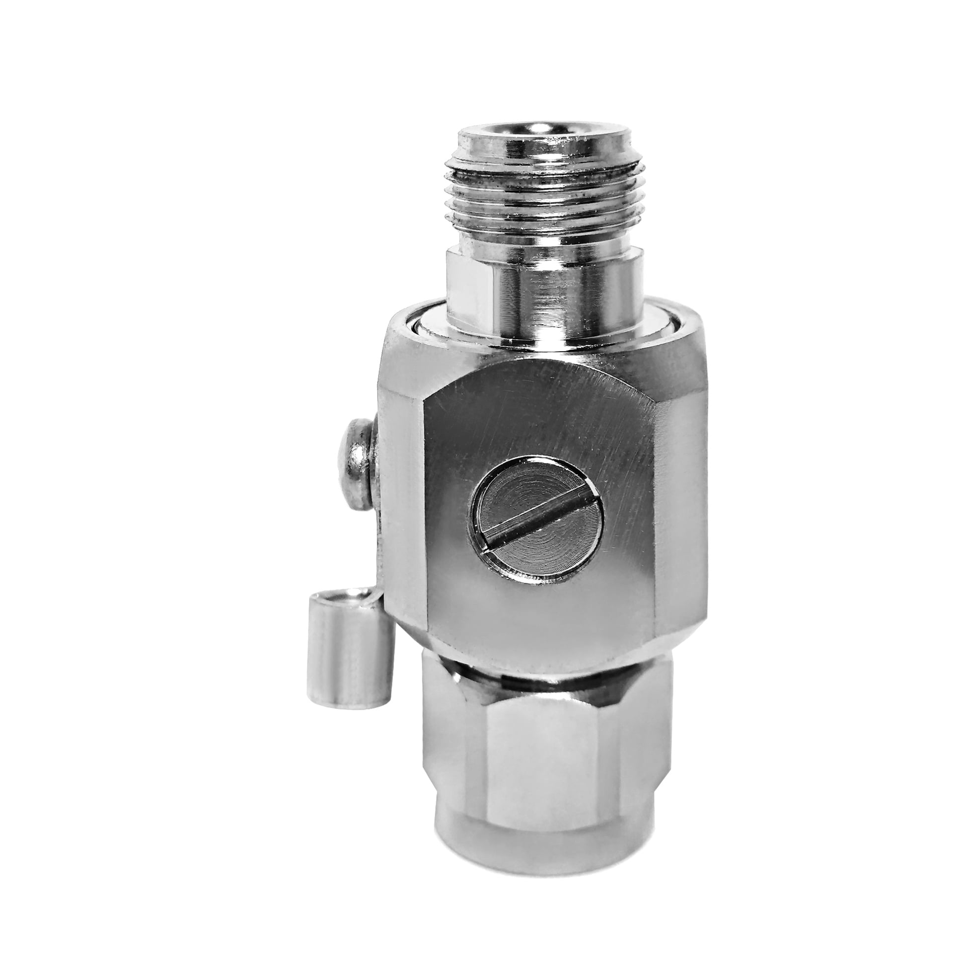
This N Male to N Female lightning arrester is a GDT based RF surge protector designed for DC - 3 GHz operation. It sits in the transmission line between the antenna and the radio equipment, diverting lightning-induced transients to ground before they reach the sensitive front end. The 50 ohm design holds insertion loss at 0.2 dB with a VSWR of 1.25 or better across the passband.

Request a Quote  |  Download Datasheet  |  Ask an Engineer

Request a Quote WhatsApp
  • Overview

Overview

Product Overview

The N Male to N Female lightning arrester is an in-line RF surge protector for 50 ohm antenna and transmission-line systems operating from DC to 3 GHz. It uses a replaceable 90 V gas discharge tube (GDT) to direct lightning-induced and switching transients toward the grounding point before they reach connected radio equipment. In normal service, the GDT remains electrically inactive and supports a low-loss RF path. The stated insertion loss is 0.2 dB across the passband, helping the device fit installations where signal continuity matters as much as surge diversion.


This N Male to N Female lightning arrester is designed for applications that need a practical connection between standard N-type cable assemblies and a defined earth path. Its gas-tube design keeps capacitance low compared with many diode-based approaches, which supports operation over a broad DC–3 GHz range. After a significant surge event, the discharge tube can be assessed and replaced when required instead of replacing the complete protector. Final performance and configuration should always be checked against the production version selected for the project.


Protection Mechanism and Construction

  • Protection Element: The central protection element is a 90 V gas discharge tube rated for a reference surge current of 10 kA on an 8/20 µs waveform. When a transient exceeds the operating threshold, the tube ionizes and creates a route for surge energy to move away from the RF equipment path.
  • Grounding Path: A side-mounted ring terminal provides the connection point for the earth conductor. The effectiveness of any RF surge protector depends on the complete grounding arrangement, so the lead from the N Male to N Female lightning arrester to the earth bar should be short, direct, and appropriately sized for the installation.
  • Body: The body is machined brass with corrosion-resistant plating. Its square-flange configuration supports fixed mounting on a panel, bulkhead, cabinet, or equipment enclosure where a stable mechanical position and accessible ground connection are needed.
  • Connector Interface: The product provides an N Male to N Female interface for use with standard RF cable assemblies. The connection arrangement allows the protector to be placed in an existing coaxial line without changing the mating connector type at the protected equipment side.


Reference Technical Specifications

The values below describe the reference configuration of this N Male to N Female lightning arrester. They are intended to help engineers compare the product with system requirements and should be confirmed for the final production configuration before installation or procurement.

Parameter Specification Notes
Connector Interface N Male to N Female Standard RF connector
Mounting Style Square Flange Body configuration
Impedance 50 ohm System impedance
Frequency Range DC – 3 GHz Passband
Insertion Loss 0.2 dB Across passband
VSWR 1.25 Maximum reference value
Power Handling 200 W CW, reference
Discharge Element 90 V Gas discharge tube
Surge Current 10 kA (8/20 µs) Reference waveform
Grounding Ring terminal M4 lug, ground wire
Body Material Machined brass Corrosion-resistant plating
Weight 130.3 g Approximate
Typical Application Cabinet mounting, BTS shelter, equipment chassis Primary use case

Reference values are based on the available information for this protection family. The selected production version remains the authority for configuration-specific technical confirmation.


Engineering Comparison

  • Compared with a quarter-wave stub: A quarter-wave solution is tuned around a limited frequency range and has a different DC behavior. This N Male to N Female lightning arrester provides a DC–3 GHz passband, making it suitable for sites that use more than one radio band or require a broad operating range in the same protection position.
  • Compared with a diode-based protector: Diode designs can provide different clamping characteristics, but added capacitance may influence high-frequency or high-power RF use. The GDT-based RF surge protector is specified with 0.2 dB insertion loss and 200 W reference power handling for transmission-line applications where low signal disturbance is important.
  • Compared with a DC-block device: A DC block controls DC continuity but is not a substitute for an earth path designed to divert a high-energy surge. The ring-terminal ground connection on this N Male to N Female lightning arrester is central to its function in outdoor antenna-line protection.


Applications

  • Cabinet mounting, BTS shelter, and equipment chassis: Install the RF surge protector at the cable entry or equipment-side connection to help limit transients coupled onto the antenna line before they reach radio hardware.
  • Tower and rooftop installations: The protector can be positioned where an outdoor cable enters a shelter, cabinet, or protected equipment area, provided that the grounding system is designed and maintained for the site.
  • Multi-band radio sites: The stated DC–3 GHz range supports installations with broad or changing frequency requirements without using a separate narrowly tuned protection component for each listed band.
  • Equipment racks and test systems: In long cable runs, induced transients can travel toward sensitive modules and instruments. Placing the N Male to N Female lightning arrester at the equipment input adds a defined protection point in the coaxial path.


Installation and Grounding Notes

  • Grounding First: Connect the ring terminal to the earth bar using the shortest practical route. Excess lead length and unnecessary bends add inductance, reducing the usefulness of the RF surge protector during a fast transient.
  • Mounting: Secure the square-flange body so that the connectors, ground lug, and cable route remain accessible for inspection. Locate the protector within the applicable protected zone of the site lightning-protection arrangement.
  • Torque and Sealing: Tighten N-type connections according to the connector manufacturer’s requirements. Where the connection is exposed to weather, use appropriate sealing practices around the connector interface.


OEM and B2B Support

  • Configuration Review: For volume projects, confirm the required connector combination, discharge-voltage option, and plating requirement against the final production configuration.
  • Cable Assembly Planning: Evaluate the cable route, mating interfaces, and installation position so the N Male to N Female lightning arrester can be integrated into the intended assembly.
  • Project Documentation: Confirm any packaging, labeling, or batch-documentation requirements with the supplier before placing a project order.


FAQ

Q: How often does the gas discharge tube need replacement?

A: The 90 V gas discharge tube is rated for a 10 kA (8/20 µs) reference surge current. Following a major surge event, inspect or test the tube according to the applicable maintenance procedure. If it no longer meets the required condition, it can be replaced without replacing the entire arrester.


Q: Will this N Male to N Female lightning arrester affect a DC–3 GHz signal?

A: The reference insertion loss is 0.2 dB, with a stated maximum VSWR of 1.25 across the passband. Actual RF impact should be evaluated against the final product configuration and the complete transmission-line system.


Q: Can this arrester be used indoors?

A: Yes. It may be installed at the equipment end of a cable run as well as near an entry point when the system design calls for that protection position. Proper grounding remains essential in either location.

Featured Products