 EN
EN

What environmental resistance can be customized for OEM rf cable
2026/09/25
Customize an rf high frequency cable for temperature, moisture, corrosion, vibration, flexing, and OEM validation needs.
2026/09/09
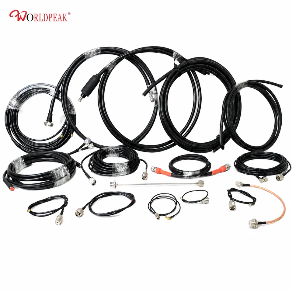
Coaxial cable assembly forms the backbone of every high-performing radio frequency system. Whether tuning a marine VHF setup, configuring an amateur radio shack, or setting up a commercial land mobile radio antenna, the quality of your cable termination dictates signal efficiency. At the heart of lower-frequency RF systems sits the time-tested PL-259 connector, widely recognized in technical circles as the classic male UHF connector.
Despite decades of engineering advancements in snap-on and precision microwave fittings, the PL-259 connector remains an industry workhorse. Its heavy-duty brass construction, rugged threaded coupling, and forgiving dimensions make it an ideal choice for high-power, sub-300 MHz applications. However, behind its simple threaded exterior lies an assembly process that leaves zero room for error. A single cold joint or a stray braid strand can trigger unexpected standing wave ratios, ruin power transfer, or destroy sensitive transmitter finals.
Understanding how to prep, solder, and protect these connectors ensures your communications remain clear, weather-resistant, and efficient over years of tough service.
Begin by stripping approximately 1.5 inches (38 mm) of the outer PVC or PE jacket from large-diameter coax like RG-8, RG-213, or LMR-400. Carefully cut through the insulation without nicking the underlying copper braid. Once the jacket is cleared, trim the inner foam or solid dielectric, leaving about 0.75 inches (19 mm) of exposed center conductor. Clean, straight cuts keep the cable centered when sliding into the shell.
Comb the exposed metallic braid outward into individual strands, ensuring no loose wires cling to the inner dielectric. Gently fold the braid backward, wrapping it tightly over the remaining outer jacket. This folding action creates the ground contact area inside the body of the connector pl259. A smooth fold prevents binding when threading the connector body home.
Tin the exposed copper center conductor with a light layer of rosin-core solder before fitting the main body over the dielectric. Slide the center pin onto the tinned wire. Using a heavy-duty soldering iron rated for at least 100 watts, apply heat directly to the tip of the center pin. Introduce solder through the end hole until the hollow pin fills completely, forming a concave, mirror-bright solder fillet.
Thread the main connector body firmly over the folded braid until the center pin seats flush at the front nose. Locate the four solder inspection holes around the body shoulder. Apply a high-wattage iron tip to each hole in turn, heating the brass body enough to draw solder inside onto the trapped braid. Allow each port to cool naturally to avoid internal plastic deformation.
Slide the threaded coupling ring forward over the assembly, ensuring smooth engagement on the 5/8-24 threads without cross-threading. For exterior installations, wrap the finished assembly starting 2 inches below the connector with self-amalgamating silicone tape, followed by a protective layer of UV-resistant electrical tape or adhesive-lined heat-shrink tubing.
To get the best performance from any RF system, you need to match the connector to its operating limits. The PL-259 connector works alongside its matching jack, the pl259 female connector, commonly known in the industry as the SO-239 socket.
| Technical Parameter | Specification Value | Field Impact & Notes |
|---|---|---|
| Nominal Impedance | ~50 Ohms (Non-constant) | Perfect for HF/VHF; slight impedance bump at UHF |
| Frequency Range | DC to 300 MHz | Performance drops sharply above 300 MHz |
| Thread Size | 5/8-24 UNEF Thread | Standardized threading fits all SO-239 sockets |
| Power Handling | Up to 1500W PEP | Ideal for high-power HF linear amplifiers |
| Dielectric Material | PTFE (Teflon) or Delrin | High heat tolerance during heavy soldering |
Because the internal dimensions of a PL-259 connector do not maintain a constant 50-ohm geometry across its entire length, subtle impedance bumps occur at higher frequencies. Below 30 MHz in HF ham bands, these variations are negligible. Up to 150 MHz in marine VHF setups, signal loss stays well within acceptable margins. Above 300 MHz, however, modern precision fittings like N-type or BNC connectors generally replace UHF designs to keep insertion loss low.
Even experienced technicians occasionally run into problems when installing a PL-259 solder connector under tough field conditions. Avoiding these primary failure modes keeps system performance stable and maintenance costs low:
A solid PL-259 plug requires an equally dependable mating partner. The pl259 female connector comes in several configurations depending on the enclosure design and structural mounting needs:
Offshore marine installations put RF connectors through extreme stress. Constant saltwater spray, high humidity, continuous vibration, and thermal cycling destroy poorly prepped connections.
During a recent communication upgrade on a 45-foot sailing vessel, field technicians replaced degraded feedlines with silver-plated PL-259 connector units featuring full PTFE insulation. Every solder port received high-purity rosin-core solder, followed by silicone dielectric grease smeared across the external threads to block moisture ingress. Adhesive-lined heat-shrink tubing sealed the junction where the coax jacket met the connector base.
Inspected after three full years of ocean operation, the connections showed zero signs of green copper corrosion, and the system maintained a flat 1.15:1 SWR reading across all marine VHF channels.
High-performance RF installations rely on consistent, high-precision manufacturing. Varied wall thicknesses, out-of-spec thread tolerances, or cheap plating on budget connectors degrade signal pathways and cause assembly headaches during field repairs.
Worldpeak addresses these critical needs through advanced manufacturing processes, precision CNC machining, and rigorous quality control standards. Offering a comprehensive portfolio of connector pl259 plugs, pl259 female connector sockets, panel jacks, and specialized RF adapters, Worldpeak utilizes top-tier materials including solid brass bodies, heavy silver or gold contact plating, and high-temp PTFE dielectric cores.
For mission-critical operations requiring turnkey solutions, Worldpeak also provides factory-tested custom coaxial jumper assemblies. Built with automated stripping and precision soldering systems, every assembly undergoes 100% SWR and insertion-loss testing before shipment. Whether building marine comms networks, commercial land-mobile infrastructure, or high-power radio shacks, partnering with an experienced RF manufacturer like Worldpeak ensures long-term transmission reliability across every link in your signal chain.

2026/09/25
Customize an rf high frequency cable for temperature, moisture, corrosion, vibration, flexing, and OEM validation needs.

2026/09/25
Streamline RF equipment assembly lines with custom coaxial jumpers. Reduce line-side rework, ensure precise routing, and boost production efficiency.

2026/09/25
Learn PL-259 connector selection, soldering, weatherproofing, and RF applications for dependable antenna feedlines.

2026/09/25
Confirm impedance for a 90 degree coax connector with an ODM test plan covering VNA setup, VSWR, acceptance criteria, and release records.

2026/09/25
Learn when an n type coax connector can omit extra anti-corrosion treatment and when OEM exposure conditions require it.

2026/09/25
Learn how the custom cable and wire sample process helps ODM buyers validate design, testing, and production readiness.