 EN
EN

7/16 DIN Connector Guide: High-Power RF Standard
2026/09/24
Choose a 7 16 connector for high-power RF: compare DIN and Type N, protect PIM margin, and apply field installation checks.
2026/09/21
In the RF link, connectors are never simply "connectors". They are the key nodes for impedance matching of the entire system and the weak links that are most prone to introduce hidden errors. Today, we will explain the structural principles, selection logic, fatal compatibility misconceptions, and standard assembly processes of RF connectors from a frontline practical perspective, all of which are practical knowledge that can be used in engineering.
1.Core structure and underlying mechanism of RF connector mismatch
The 50 Ω coaxial RF connectors we commonly use have a unified structural logic: inner conductor, supporting medium, outer conductor, and locking structure four piece set. Each performs their own duties, and a lack of one will lead to problems.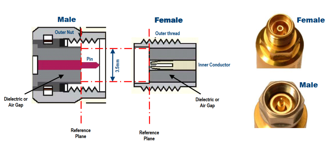
The inner conductor is responsible for transmitting RF signals, the outer conductor is responsible for shielding and grounding, and the medium in between is the core key. Its function is to firmly fix the relative concentricity of the inner and outer conductors, ensuring that the impedance of the entire link is stable at 50 Ω. The locking structure ensures the mechanical strength after docking and prevents contact loosening caused by vibration and pulling.
Many people think that connectors are straight through with zero loss, but that's not true. In an ideal state, the impedance of the entire link is constant, and the signal has no reflection or additional loss. But in actual assembly and use, as long as there is docking, there will be impedance discontinuity.
The gaps between the male and female connectors, the breakpoints of the medium segmentation, the small tolerances caused by processing, the wear of the pins after use, and the oxidation and dust on the end face can all cause the local impedance to deviate from the standard of 50 Ω. This subtle mismatch does not have a significant impact at low frequencies, but the higher the frequency, the shorter the wavelength, and even small structural defects will be infinitely amplified, directly leading to deterioration of standing waves, increased reflection, and drift of test data.
This is also the fundamental reason why millimeter wave connectors are extremely demanding on concentricity, end face cleanliness, and processing accuracy - in high-frequency systems, even a slight flaw in the connector is a hard loss of overall performance.
2.Common RF connector categories, frequency characteristics, and applicable scenarios
The upper frequency limit of RF connectors, remember a core practical rule: the smaller the size, the higher the cutoff frequency, the higher the precision requirement, and the more delicate it is. There is no good or bad distinction between different interfaces, only whether they are suitable for the scene or not. Choosing the wrong interface, even high-end devices cannot achieve their performance.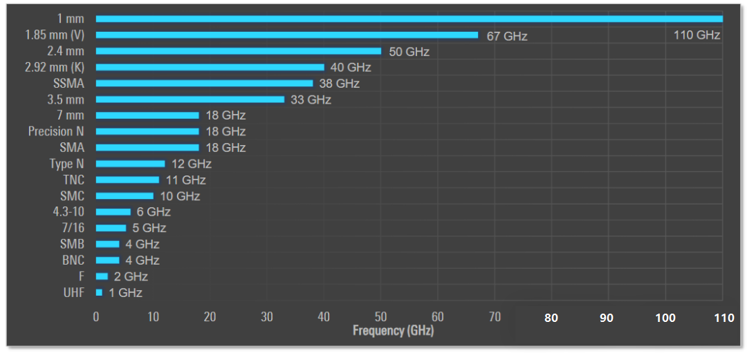
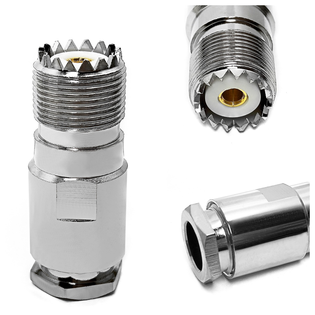
UHF is an old low-frequency interface, with a maximum of only 1GHz and poor impedance stability. Currently, only shortwave radio stations and amateur radio stations are still in use, and commercial communication and precision testing scenarios are completely eliminated. It is not recommended to use it for new projects.
Type F is well-known to everyone, specifically designed for home cable TV, with 2GHz or less being sufficient for use. Its advantage lies in its affordability and ease of use, but RF equipment development is basically unnecessary, with a dedicated interface for civilian use.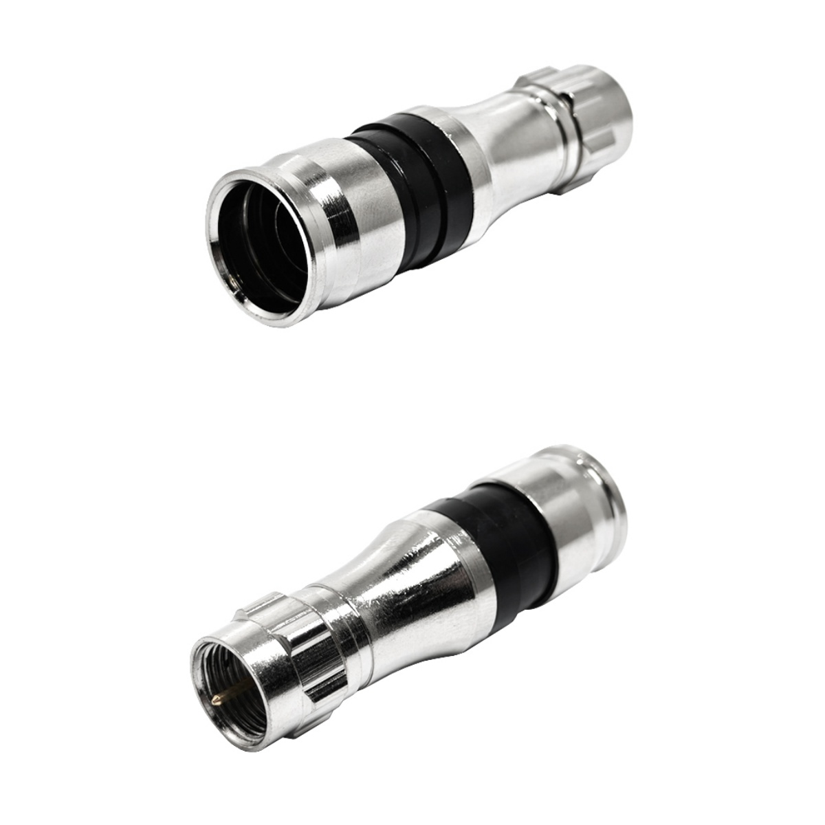
BNC is an old acquaintance in the laboratory, with a 4GHz bandwidth, snap on plug-in, fast disassembly, and stable connection. It is very suitable for desktop low-frequency testing and monitoring RF circuits. The disadvantage is that the bandwidth is limited and high-frequency scenarios are directly eliminated. The upgraded TNC has been changed to thread locking, with full anti vibration performance and increased bandwidth to 11GHz. It is commonly used in outdoor industrial equipment.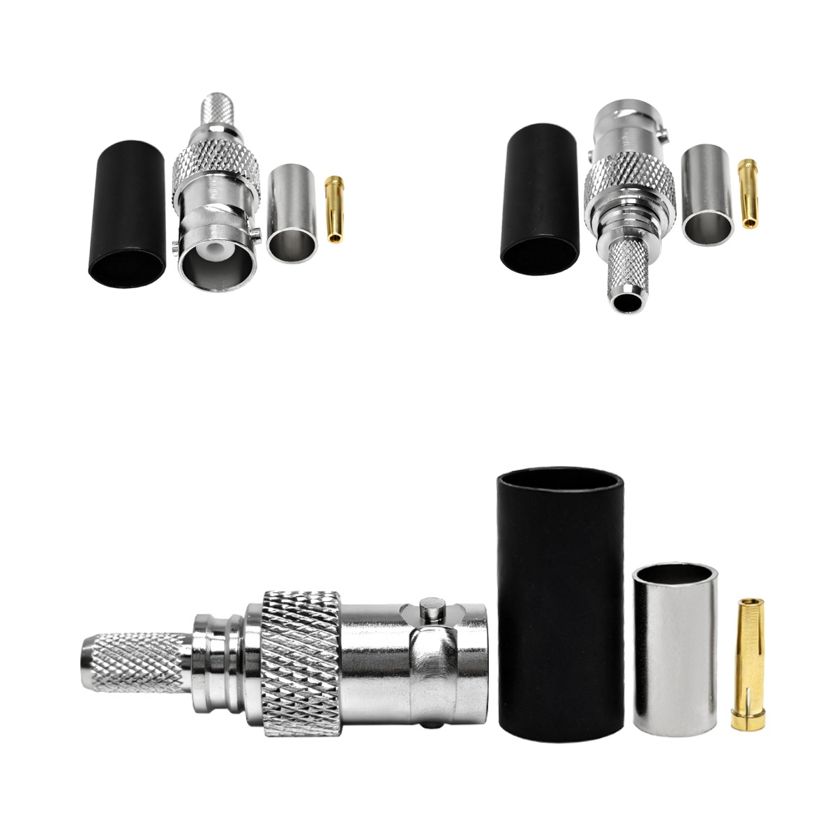
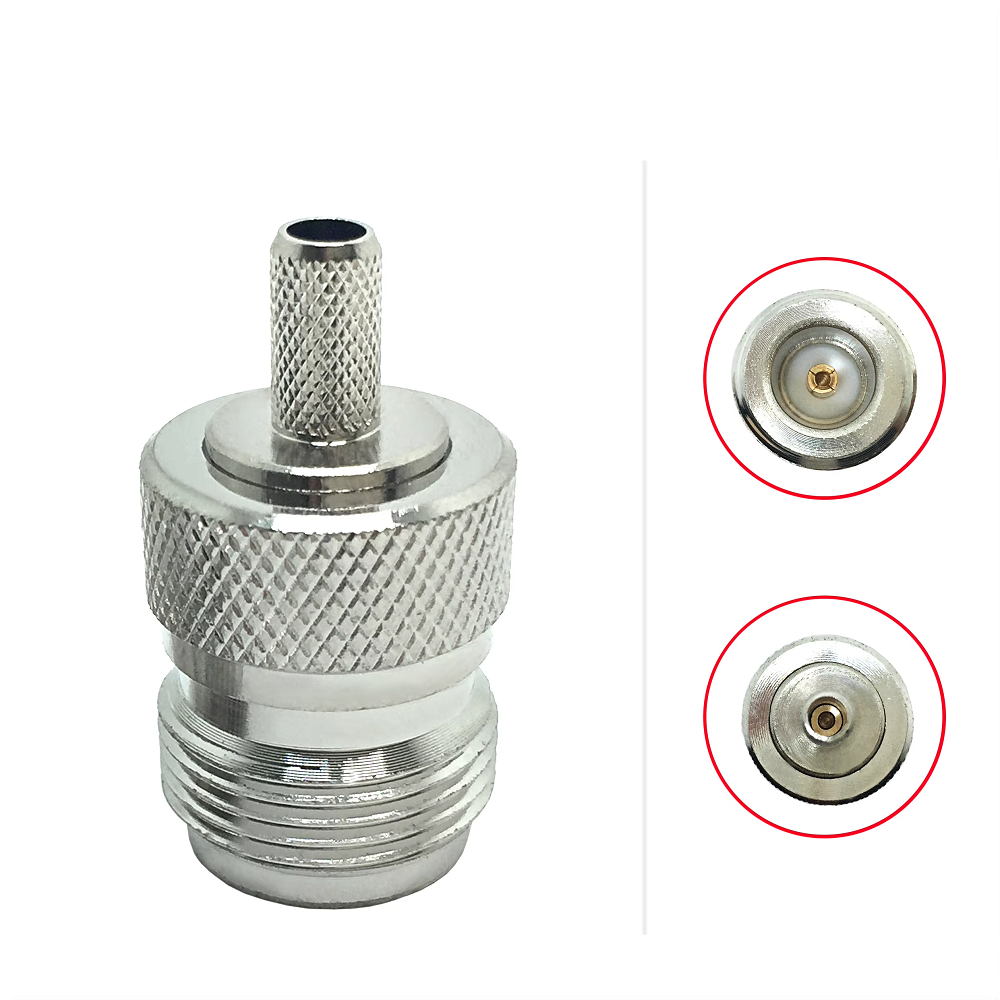
Type N is definitely the king of engineering durability. With 12GHz bandwidth, leather is resistant to manufacturing, high and low temperatures, and aging. Outdoor base stations, outdoor equipment, and conventional RF tests can all be carried out. For scenes that are unfriendly and easy to bump during on-site debugging, type N can never be wrong.
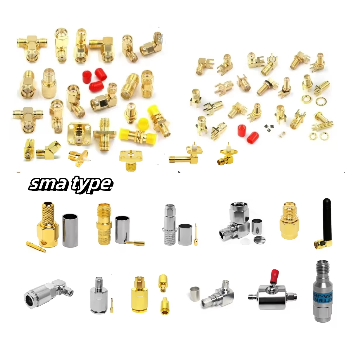
SMA is currently the mainstream in general scenarios, with a bandwidth of 18GHz, compact size, and high cost-effectiveness. It covers module prototypes, indoor RF equipment, and routine laboratory testing, and is also the interface that people come into contact with the most in their daily lives.
Entering the millimeter wave field, connectors begin to become delicate, and accuracy directly determines the success or failure of testing: 3.5mm supports 33GHz and is suitable for millimeter wave pre research testing; 2.92mm (K-type) can reach 40GHz and is the main force for 40G ultra wideband testing; 2.4mm and 1.85mm respectively cover high-frequency scenes at 50GHz and 67GHz; 1.0mm can achieve 110GHz and is specifically used for ultra precision testing such as terahertz. This type of high-frequency interface cannot be treated with the same logic as ordinary SMA.
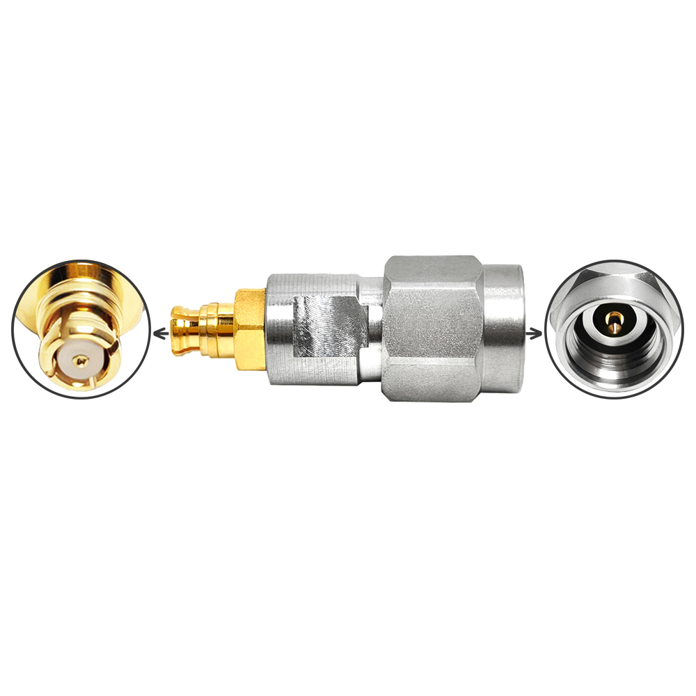
In addition, 7/16 DIN and 4.3-10 are dedicated interfaces for base station feeders, featuring high power and low intermodulation; SMC and SSMA micro interfaces, with extremely small size, are suitable for dense interconnection between internal boards of devices, each performing its own duties, and the scenarios cannot be mixed.
3、 Core knowledge point for avoiding pitfalls: Mechanical compatibility does not necessarily mean electrical compatibility
This is the most high-frequency, deadly, and easily overlooked pitfall in the entire RF industry, and it is also the place where beginners are most likely to stumble.
Many people have found that SMA, 3.5mm, and 2.92mm can be directly screwed together with perfectly matched threads, so they think they can be used interchangeably. Here, the carpenter solemnly reminds us that being able to screw it in does not mean it can be used, nor does it mean it can be used for a long time. Mechanical compatibility ≠ electrical compatibility.
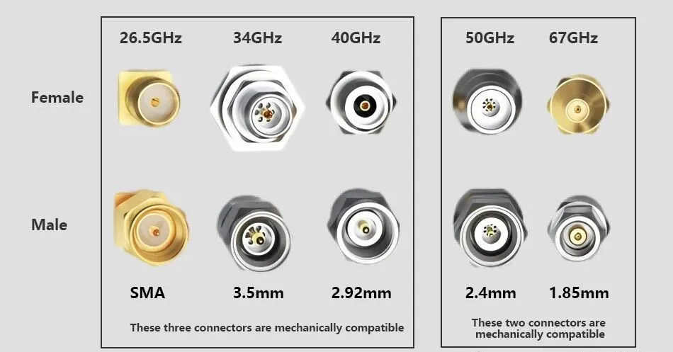
The three threads have the same outer diameter, which cannot be distinguished by the naked eye, but the internal pin diameter, spring structure, and coaxial accuracy are vastly different. The only safe compatibility logic is that the high-frequency male head can be temporarily connected to the low-frequency female head, such as connecting the 3.5mm male head to the SMA female head, which is not a problem for emergency use.
But reverse docking is absolutely prohibited: SMA male heads must not be inserted into 3.5mm or 2.92mm female heads! SMA pins are thicker and have larger tolerances. If forcibly screwed in, they will directly scratch and support the precision elastic spring of the high-frequency female head. This type of damage is permanent and irreversible. Once the spring is deformed or has poor contact, the standing wave at the port will be directly scrapped, causing damage to high-frequency testing ports that can easily reach thousands or tens of thousands, which is not worth the loss.
Similarly, 2.4mm and 1.85mm millimeter wave interfaces can also be mechanically compatible, but the accuracy levels are completely different. Mixing them will damage coaxiality, introduce huge reflection errors, and completely distort millimeter wave test data.
Frontline practical guidelines: All precision high-frequency interfaces must be properly labeled and paired with the same model for use. It is strictly prohibited to use low-frequency male connectors against high-frequency female connectors.
4.Standardized torque specifications and professional assembly processes
Many people use genuine and high-quality equipment, cables, and connectors, but the indicators are still very poor, and the problem lies entirely in the assembly habit of "casually twisting".
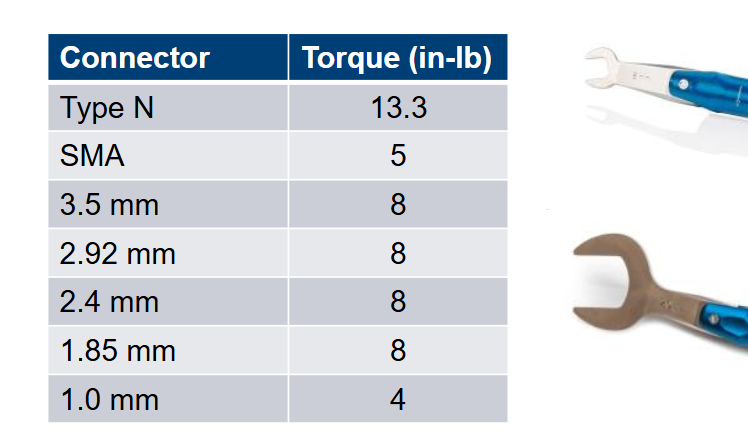
Connector assembly, torque is the lifeline. Hand twisting and feeling is a major taboo in RF engineering. The torque is reduced, the contact between the male and female ends is not solid, the contact resistance increases, and the standing wave drifts back and forth during vibration and temperature changes, resulting in extremely unstable data; The torque has been tightened too much, causing thread slippage, medium pressure deformation, spring compression failure, and the connector to be scrapped directly.
Here is a list of universal torque standards for everyone, which can be directly copied and used:
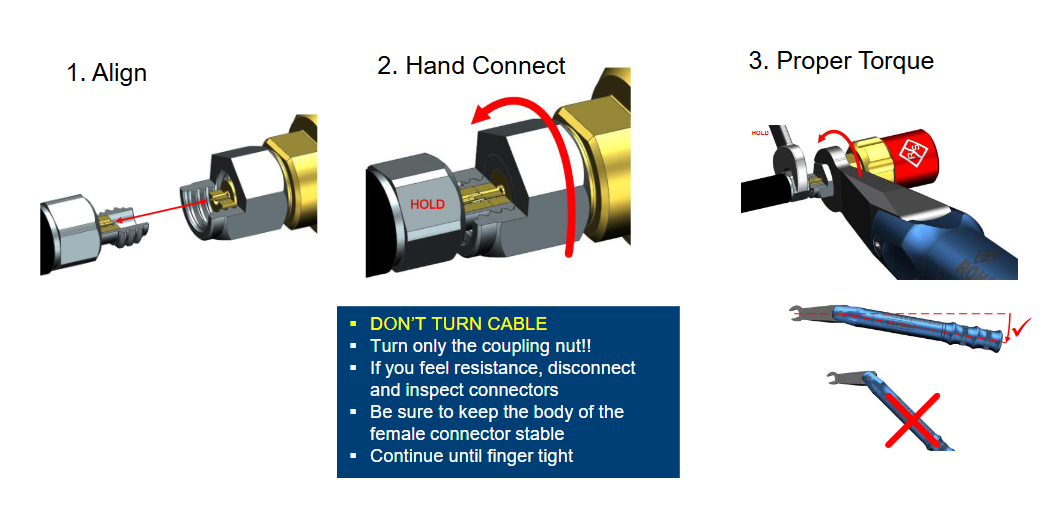
In addition to torque, the standardized assembly process must be followed, which is the practical three-step method summarized by the experienced engineer:
The first step is to align the male and female heads, and they should be straight and connected. They must not be twisted or bent, as even a slight tilt can cause the internal thin pins to bend; Step 2: Pre tighten by hand, fix the cable body, only turn the nut, and strictly prohibit turning the cable joint to avoid twisting, desoldering, or misalignment of the internal conductor; The third step is to tighten the torque by using a specialized torque wrench to apply horizontal force until it clicks and stops immediately, without over tightening or under tightening.
Finally, three assembly red lines are reiterated: manual and violent tightening is prohibited, forced docking at oblique angles is prohibited, and locking joints by rotating cables is prohibited. All inexplicable unstable links have basically stepped into these pitfalls.
5.Core selection principles for engineering implementation
Firstly, prioritize frequency and reserve sufficient margin. The maximum operating frequency of the system must not be used against the upper limit of the connector. For example, when the device operates at 20GHz, it must not use an 18GHz SMA and must be connected to a 3.5mm interface. Full load use will lead to a sharp deterioration of standing wave and loss indicators, and stability cannot be guaranteed at all.
Secondly, scene matching and on-demand selection. For outdoor high-power and high vibration scenarios, priority should be given to interfaces with sturdy structures and resistance to environmental interference such as N-type, 4.3-10, and TNC; Internal miniaturization interconnection of devices, using SMA and SMC micro interfaces; Laboratory precision testing and millimeter wave research and development must use high-frequency precision connectors of the corresponding level, and will never be downgraded or replaced.
Thirdly, pay attention to daily protective maintenance. Precision RF interfaces are most afraid of dust, scratches, and bare placement. When idle, it is necessary to wear a dust cap and regularly check whether the end face is dirty, whether the pins are worn, and whether the spring is loose. Many devices deteriorate as they are used, not due to device aging, but rather due to the accumulation of dust and minor damage from long-term exposed connectors.
6. Conclusion
Chips, antennas, and filters determine how well a system can run, while connectors, cables, and other inconspicuous passive components determine whether the system can be stable, reliable, and work for a long time. Many engineers spend a lot of time debugging indicators and troubleshooting bugs, only to discover that it is just a small connector pairing error, non-standard assembly, and mismatched selection grade.
A seemingly simple connector that covers the entire logic of structural principles, impedance matching, assembly processes, and brand selection. By understanding principles, being able to select models, adhering to standards, and distinguishing between different levels, you can solidify every interconnection detail. Your RF equipment and testing system will improve in performance, stability, and mass production reliability to a higher level.
Chips, antennas, and filters determine how well a system can run, while connectors, cables, and other inconspicuous passive components determine whether the system can be stable, reliable, and work for a long time. Many engineers spend a lot of time debugging metrics and troubleshooting bugs, only to find out that it's just a small connector pairing error and improper assembly.
Seemingly simple docking operations conceal the underlying logic of the RF system. By understanding the principles, being able to select models, adhering to standards, and avoiding misunderstandings, and making every detail of interconnection solid, the performance and stability of your RF equipment and testing system will be improved to a higher level.

2026/09/24
Choose a 7 16 connector for high-power RF: compare DIN and Type N, protect PIM margin, and apply field installation checks.

2026/09/24
Compare TNC connector types, specs and applications, including RP-TNC, bulkhead options, vibration performance and adapter selection.

2026/09/24
Understand MMCX connector basics, RF limits, and how to choose the right coaxial interface for compact systems.

2026/09/24
Understand RP-SMA connector polarity, mating rules, frequency checks, and OEM termination options for reliable RF builds.

2026/09/24
Choose the right bnc male connector for RF, CCTV and test systems with clear 50Ω vs 75Ω, type and installation guidance.

2026/09/24
Compare LMR400 specs, cable loss, uses, connectors and RG8/RG213 alternatives with a practical RF loss-budget method.