 EN
EN

RF Technology Components: Overview for System Designers
As an RF systems engineer who has designed signal chain deployments across base station infrastructure and defense electronics, I've found that understanding rf technology components and systems at the integration level is what separates successful deployments from expensive rework. What changed my thinking early on was realizing that most integration failures trace back to passive components inadequately specified for the operating environment—not to the active devices everyone watches most closely.
The global RF component market reached USD 46.5 billion in 2024, with the passive segment alone at USD 18.3 billion—both expanding at double-digit rates driven by 5G deployment. Each 5G base station consumes approximately 400 passive components to maintain signal integrity across the full frequency chain. This demand profile makes a clear-eyed understanding of rf technology components and systems essential for anyone managing RF procurement or integration today.
This overview covers the passive building blocks most commonly specified by system designers: couplers, attenuators, filters, isolators, and circulators. For each, I'll address working frequency range, insertion loss, and power capacity—the three parameters that matter most at the system level. I'll also cover how rf connectors and adapters serve as the integration interfaces for all other passive components, where OEM customization adds value, and how these components map across three main application verticals: 5G infrastructure, military electronics, and test and measurement.
Core RF Passive Component Types
Directional Couplers
Directional couplers split a portion of the RF signal for monitoring or power measurement without significantly disturbing the main path. Coupling factor—typically 10, 20, or 30 dB—defines how much signal is diverted. Insertion loss on the through path is usually below 0.5 dB at mid-range frequencies. In wideband rf technology components and systems deployments, coupling flatness across the operating band is the critical spec: 1.5 dB variation across a 5 GHz bandwidth will introduce measurement errors that compound at every monitoring point.
Attenuators
Fixed attenuators reduce signal power by a defined amount while maintaining the system's impedance match. Power capacity is the first parameter to verify: an attenuator rated at 2 W inserted between a 50 W transmitter and a test port will fail under steady-state drive. Verify the power rating at the actual power reaching the attenuator port—not the transmitter peak output.
Bandpass Filters
Filters define the passband and the stopband suppression. The transition slope determines how well the filter rejects adjacent-channel interference. Modern 5G handsets integrate up to 40 acoustic filters to isolate Wi-Fi 6E, Bluetooth, ultra-wideband, and 5G signals from one another. For base station infrastructure, cavity filters handle higher power with lower insertion loss than ceramic alternatives, making them the standard for duplexers.
RF Isolators and Circulators
RF isolators and circulators are ferrite-based components that control signal flow direction. Understanding rf isolators and circulators is particularly important for system designers building duplexer configurations: isolators pass signals in one direction while absorbing reverse-direction signals (isolation typically 18–25 dB), while rf circulators and isolators route signals in a defined rotational sequence between ports. Both component types exhibit ferrite-dependent behavior: operating temperature range is a critical secondary parameter, since ferrite permeability changes with temperature. Request temperature characterization data for outdoor or airborne installations rather than relying on nominal room-temperature specifications.
RF Connectors and Adapters
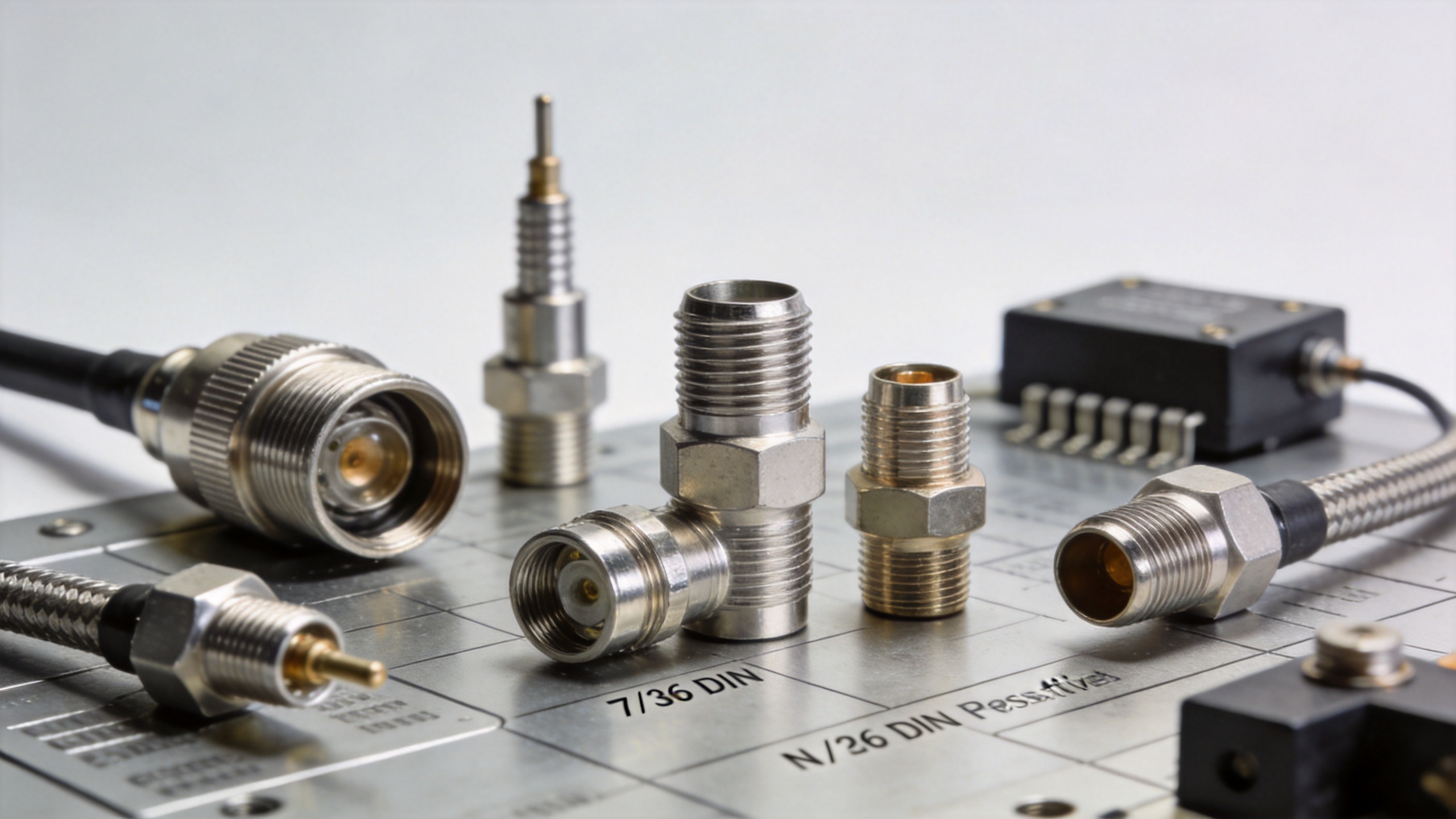
RF connectors and adapters are the physical interfaces binding all other passive components into functional assemblies. As part of the broader category of rf technology components and systems, rf connectors and adapters often receive less scrutiny than active devices—but mismatched or under-rated connectors cause failures that are difficult to diagnose after integration. Key decision variables are interface type (SMA, N-type, 7/16 DIN, TNC, BNC), frequency rating, and power handling. The RFX-Custom-02 High-Power RF Connector (7/16 DIN Female to N Male, 0–3.5 GHz, 3 kW @ 2.5 GHz) illustrates that silver-plated brass construction and IEC 61169-4 compliance are baseline requirements for high-power infrastructure connectors, not optional upgrades.
Key Selection Parameters
Working Frequency
Every passive component has a defined operating range. A component meeting specification at 2 GHz may fail at 18 GHz due to parasitic effects from the same physical geometry. If the system operates from 0.5 to 6 GHz, a component rated to 6 GHz maximum leaves no aging margin at the top of the band. This applies consistently across rf technology components and systems—from connectors to filters to isolators.
Insertion Loss
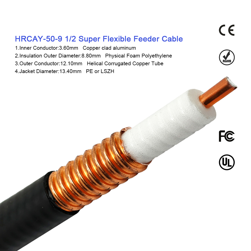
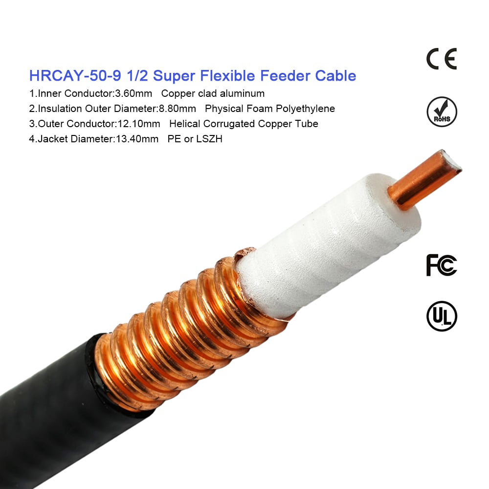
In a cascaded system with ten passive components each contributing 0.3 dB insertion loss, cumulative path loss reaches 3 dB—equivalent to halving received signal power. Every passive element must be accounted for in the link budget. Feeder cable runs add to this total: the 1/2" Superflex Corrugated Copper Feeder Cable (50 Ohm) is optimized for low insertion loss per meter on long base station feeder runs, where per-meter loss accumulates directly against link margin.
Power Capacity
Power handling limits arise from two mechanisms: average power (thermal dissipation) and peak power (voltage breakdown risk). Telecom infrastructure typically applies a 3 dB derating margin; military and space applications require 6–10 dB under MIL-spec conditions.
Industry Applications
5G infrastructure deployments push component requirements harder than previous generations: higher operating frequencies and Massive MIMO arrays demand lower insertion loss, tighter phase tracking, and better temperature stability than 4G-era hardware provided. Military and defense applications layer additional requirements on top—MIL-STD-461 and MIL-STD-810 compliance, plus rf isolators and circulators specified at 30 dB isolation or greater to keep transmit leakage from degrading co-located receivers. Test and measurement is a different discipline entirely: here, attenuators serving as calibration standards carry accuracy specs of ±0.05 dB or better, with traceability to national measurement standards that infrastructure-grade tolerances don't approach.
Component Selection Framework for RF System Integrators
There is no universally optimal passive component—the right choice depends on operating frequency and the required performance margin for your system environment. When working with rf technology components and systems for integration projects, the following selection sequence is practical:
- Define the frequency range, including any plan changes within the system's service life.
- Set the insertion loss budget based on the link budget; leave 1–2 dB margin for aging and temperature effects.
- Verify power handling at the actual operating point, not the transmitter rated output. Apply appropriate derating margin for the application category.
- Confirm environmental ratings against the actual deployment environment for temperature, IP rating, and vibration requirements.
- Specify rf connectors and adapters precisely—gender, polarity, and coupling mechanism—before issuing RFQs to avoid delivery of physically incompatible assemblies.
Approaching component selection at the system level—rather than evaluating each rf technology component against its own datasheet in isolation—is what separates signal chains that perform consistently in the field from those that pass bench testing but fail after deployment. For applications requiring components outside standard catalog specifications, OEM customization across connector interface, frequency range, and power rating is worth evaluating early in the design cycle.





