 EN
EN

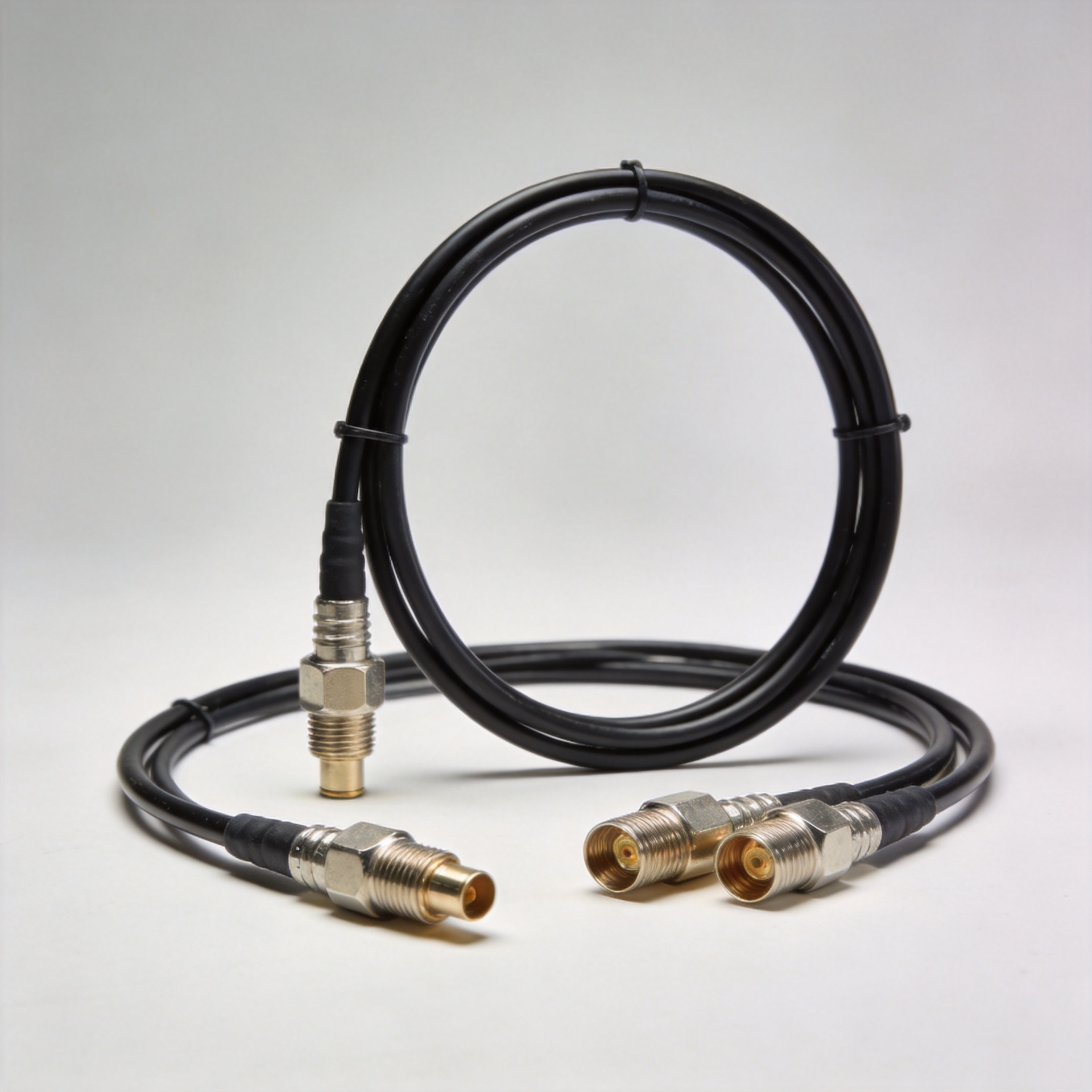
Rg Cable Types: A Complete Overview
Choosing among rg cable types is less about memorizing numbers and more about matching a transmission line to a real signal path. As an RF systems engineer, I start with impedance, operating frequency, loss budget, power, routing space, and environment. A cable that looks suitable on a purchasing list can still create mismatch loss or installation trouble once it is terminated and routed.
The RG label is useful shorthand, but it is not a complete release specification. Construction, jacket, shielding, conductor style, and performance can differ by variant and supplier. For every rg cable types decision, verify the supplier datasheet and the connectorized assembly drawing before release.
What separates common RG cable types?
Most rg cable types share the coaxial arrangement: center conductor, dielectric, shield, and jacket. Change any of those layers and you change the electrical and mechanical result. A larger center conductor and dielectric geometry can support a different impedance or power margin; a tighter braid or added foil can improve shielding; a PTFE dielectric may suit higher-temperature or higher-frequency work, while a flexible polymer system may be easier to route.
Characteristic impedance is the first gate. A 50-ohm path is common in RF instruments, antennas, radios, industrial wireless equipment, and many test systems. A 75-ohm path is common in video and distribution work. Mixing the two without a designed matching network can raise reflections, so selecting rg cable types by outer diameter alone is a costly shortcut.
Fast comparison table for procurement
| Family | Nominal impedance | Typical selection logic | Common fit |
|---|---|---|---|
| RG-58 | 50 ohm | Flexible, compact general RF runs; confirm loss at your frequency and required bend radius. | Radio links, lab leads, control cabinets |
| RG-59 | 75 ohm | Smaller 75-ohm option for lower-frequency or shorter video-style runs; verify shielding and jacket. | Legacy video and indoor distribution |
| RG-6 | 75 ohm | Choose when a 75-ohm video/distribution system needs lower loss than smaller cable, subject to installation geometry. | Video, CATV-style distribution, building runs |
| RG-196 / RG-405 class | Check the exact datasheet | Use specification-controlled RF cable or assemblies where high-frequency behavior, form factor, and repeatability matter. | Test, measurement, aerospace, compact RF assemblies |
This table is an orientation tool, not a universal limit table. Among rg cable types, frequency range, attenuation, voltage rating, power capacity, temperature range, and shielding effectiveness belong on the RFQ as explicit fields.
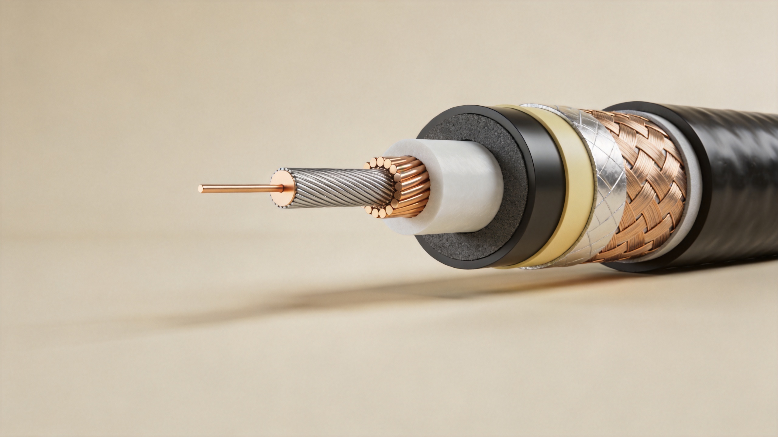
RG-58 coaxial cable: a 50-ohm practical choice
Rg 58 coaxial cable is often the familiar flexible 50-ohm option. It is useful when equipment, connectors, and source/load impedances are designed around 50 ohms and routing needs some compliance. For short instrument or radio interconnects, its manageable size can be as valuable as its electrical category.
There is a boundary to that recommendation: if the run grows long, frequency rises, or the link budget is tight, do not assume a rg 58 coaxial cable remains the economical answer. Compare attenuation at the actual operating frequency, including connector loss and any temperature derating. In industrial automation, vibration, repeated flexing, oil exposure, and cabinet bend radius should be written into the requirement as well.
RG-59 cable and RG-6 cable: 75-ohm paths
An rg 59 cable is generally considered when a 75-ohm architecture calls for a smaller, more flexible cable in relatively modest-frequency or shorter-run work. Its suitability depends on the installed environment and shield construction. Specify the desired braid, foil, jacket material, flame rating if applicable, and connector interface instead of buying an rg 59 cable by name alone.
An rg 6 cable is also a 75-ohm family and is commonly selected where a distribution or video path benefits from lower loss than a smaller alternative. An rg 6 cable may be mechanically less forgiving in constrained routing, so compare outer diameter, minimum bend radius, pull load, and connector termination method before standardizing it for field installation.
Frequency, power, and mechanical durability are connected
With rg cable types, frequency is not a single printed ceiling. Insertion loss rises with frequency and length, while connector quality, cable geometry, and bend-induced deformation can affect return loss. Power capacity also depends on frequency, ambient temperature, altitude, VSWR, duty cycle, and connector limitations. A cable acceptable for low-power control RF may not be appropriate near a transmitter output.
Mechanical durability deserves equal attention. Solid conductors can hold shape but may not tolerate repeated flexing as well as stranded constructions. Semi-rigid assemblies offer controlled routing and repeatable geometry, but they need planned bends. For defense and mobile industrial equipment, state vibration, shock, temperature, sealing, and mating-cycle expectations. The strongest rg cable types specification is one that connects electrical limits to the actual installation.
Application-based selection
Communications and industrial automation
Start with the system impedance. A 50-ohm radio, antenna, or measurement port points toward compatible 50-ohm cable families such as rg 58 coaxial cable, subject to loss and environmental checks. A 75-ohm video or distribution system calls for compatible choices such as rg 59 cable or rg 6 cable. In automation cabinets, prioritize jacket resistance, bend radius, connector retention, and serviceability alongside RF performance.
Defense, aerospace, and test measurement
These applications often demand controlled geometry, traceable documentation, stable performance through temperature and vibration, and a connector interface that matches the test setup. Legacy RG references may appear in requirements associated with MIL-C-17 heritage, but the procurement package should still state the current electrical and mechanical acceptance criteria. For compact 50-ohm work, review the verified Worldpeak RG196 50-Ohm Coaxial Cable: Engineering Data & Selection Guide as a product-specific starting point, then confirm the exact assembly need.
How to turn the comparison into an RFQ
- State system impedance and frequency band.
- Set maximum insertion loss, return-loss or VSWR expectations, power, voltage, and length.
- Define conductor, dielectric, shield, jacket, bend radius, temperature, and environmental requirements.
- Specify connector series, gender, plating, torque or mating-cycle needs, and any test documentation.
- Ask for a drawing and current datasheet for the exact part number.
When a pre-terminated format is more useful than bulk cable, the verified Worldpeak RG405 Pre-Terminated Cable Assembly can be evaluated against the same system checklist. The product title confirms an RG405 pre-terminated assembly; it does not replace confirmation of the required connector, length, or electrical limits.
Frequently Asked Questions
Are all RG cable types interchangeable?
No. Match impedance first, then confirm frequency-dependent loss, power, shielding, cable geometry, environment, and connector compatibility for the exact part.
Should I choose RG-58, RG-59, or RG-6 by price?
Price is a secondary filter. Choose the impedance and performance class required by the system, then compare qualified constructions and total installation cost.
What is the quickest buying rule?
Use the RG name to narrow the field, but release the order only after the datasheet, drawing, connector interface, and acceptance criteria match the application.
Conclusion
The useful way to compare rg cable types is to connect structure to system behavior. Use 50-ohm or 75-ohm compatibility as the first filter, then evaluate loss, power, shielding, flexibility, and durability at the actual operating conditions. That process turns rg cable types from a catalog label into a defensible engineering and procurement decision.





