 EN
EN

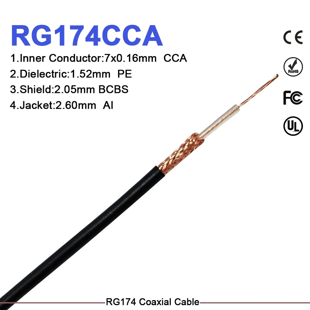
RG RF Cable: Which Grade Fits Your Frequency?
As an RF systems engineer, I have seen one selection mistake repeat itself across telecom, industrial, and lab projects: buyers choose an RG RF cable by number alone, then discover mid-integration that the physical grade does not match the application's frequency ceiling, phase stability requirement, or installation environment. The RG designation describes a cable's geometry family — diameter, dielectric, and outer conductor construction — but it does not specify whether that cable is the right grade for your operating frequency, shielding budget, or mechanical service life.
Three performance variables determine the right RG RF cable for a given application: insertion loss, shielding effectiveness, and impedance. This article maps those variables to the physical cable grades used in B2B procurement — flexible, semi-rigid, and hard-line — with a selection checklist you can take directly to an RFQ.
What the RG Designation Actually Tells You
RG stands for "Radio Guide," a classification system from U.S. military cable standards. Each RG number defines a construction geometry: outer conductor diameter, dielectric material, center conductor size, and nominal impedance. Two impedance families cover the majority of modern RG RF cable use:
- 50 Ω — the standard for active RF transmission, test instruments, and coaxial assemblies from base station feeders to precision interconnects. For solid PTFE dielectric — common in semi-rigid cable — minimum insertion loss occurs near 51–52 Ω, making 50 Ω semi-rigid with PTFE dielectric close to optimal for microwave work. The 50 Ω value itself reflects a physics compromise between minimum loss (favored around 77 Ω for air dielectric) and maximum power handling (favored near 30 Ω).
- 75 Ω — the standard for broadcast video, cable television, and satellite distribution. Cables such as RG-6, RG-6 U, and RG-179 cable sit in this family, where minimizing attenuation over long distribution runs outweighs power handling.
Mixing impedance families introduces reflections at every mismatch interface: each 50 Ω / 75 Ω transition reflects roughly 5% of the signal rather than transmitting it, a penalty that compounds across multi-connector assemblies and becomes significant above a few hundred megahertz.
Three Physical Grades Compared
Before choosing between semi-rigid and flexible RG RF cable for your design, ask one question first: how many times will this assembly be mated, routed, or adjusted during its service life? If the answer is more than a few cycles, or if the cable must flex in service, that constraint often determines the grade before any other parameter enters the evaluation.
Flexible RG RF Cable
Flexible cables use braided outer conductors that absorb repeated bending without mechanical failure. Common examples are the 75 Ω distribution grades — RG-6, RG-6 U, and RG-179 cable — alongside 50 Ω flexible grades used in short jumpers and patch assemblies.
| Parameter | Typical value |
|---|---|
| Impedance | 50 Ω or 75 Ω |
| Frequency ceiling | Up to ~3 GHz for most grades; select constructions to 6 GHz |
| Minimum bend radius | Moderate; survives repeated flex cycles |
| Phase stability under flex | Limited; unsuitable for phase-matched array applications |
| Installation | Tool-free routing; field-connectorizable |
RG-6, RG-6 U, and RG-179 cable cover CATV, satellite, and broadband distribution where long run lengths and cost-per-meter matter. For procurement teams sourcing rg rf cable for indoor antenna distribution, security surveillance, or satellite signal routing, these 75 Ω cables deliver acceptable attenuation up to 1–3 GHz. The RG-6 and RG-6 U designations differ primarily in construction refinements; most modern RG-6 coax meets or exceeds the original RG-6 U geometry. When evaluating rg rf cable for video distribution — whether RG-6, RG-6 U, or RG-179 cable — the 75 Ω impedance family is the correct starting point.
Semi-Rigid RG RF Cable
Semi-rigid cables replace the braided conductor with a seamless solid copper tube, formed once and held in shape. This construction eliminates the impedance discontinuities of braided conductors and delivers superior shielding effectiveness (exceeding 100 dB in precision grades) and electrical length stability that flexible cable cannot match.
| Parameter | Typical value |
|---|---|
| Impedance | Predominantly 50 Ω |
| Frequency ceiling | 3 GHz (RG405); up to 18 GHz for smaller-diameter grades |
| Minimum bend radius | Tight; tool-formed; not re-bendable after assembly |
| Phase stability under temperature | High; suited to phased arrays and precision measurement |
| Installation | Requires bending fixture; not field-adjustable |
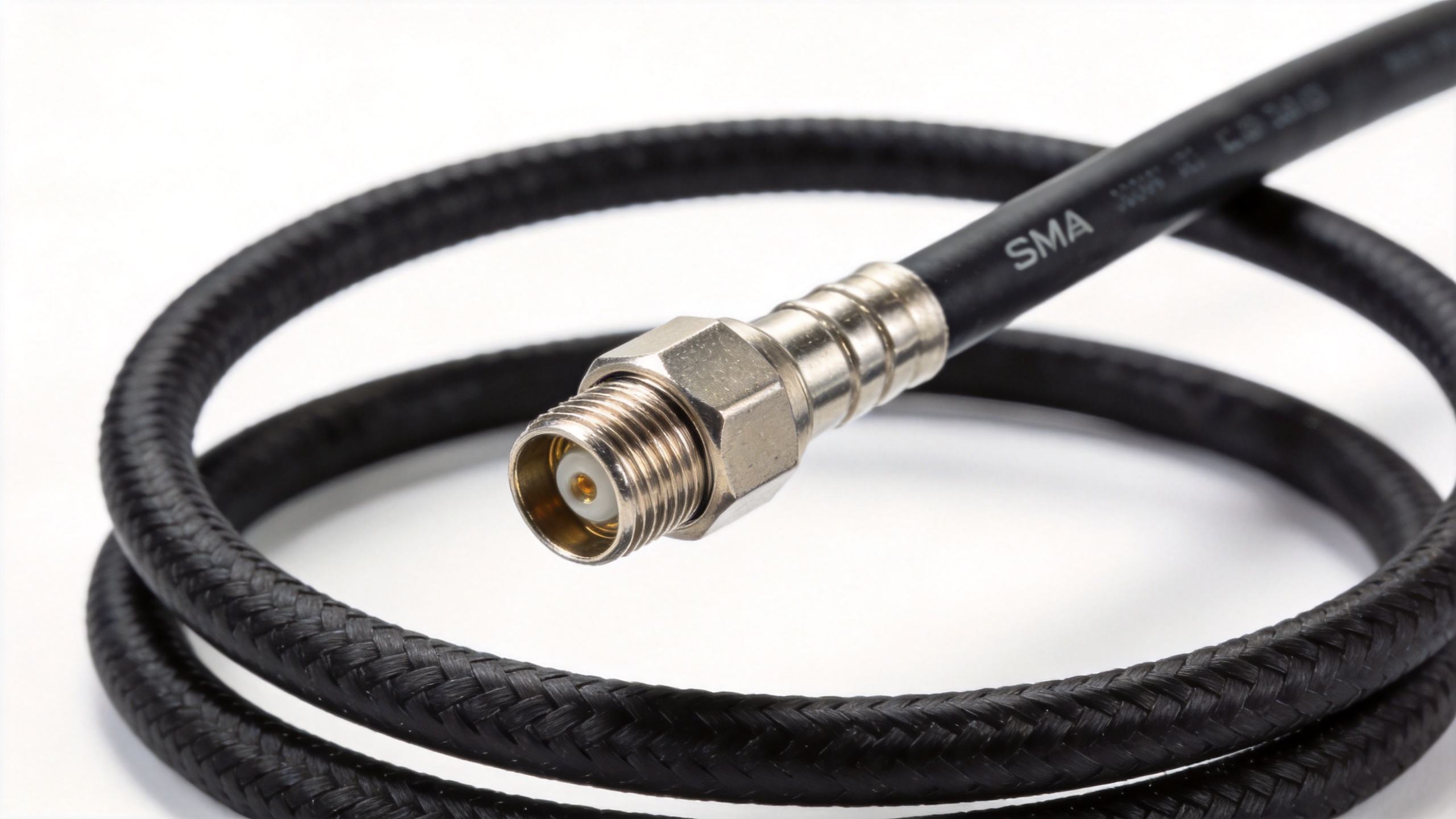
Early in my use of semi-rigid coaxial cable, I selected grades purely on insertion loss and missed the bend radius constraint — the cable could not follow the chassis routing geometry, and the rework cost exceeded any attenuation savings. Multi-constraint evaluation covering loss, phase stability, bend radius, frequency ceiling, and temperature range simultaneously is the only reliable approach.
The Worldpeak RG405 Pre-Terminated Cable Assembly is a 50 Ω semi-rigid RG RF cable rated to 3 GHz, covering -40 °C to +200 °C, with per-assembly insertion loss and VSWR test data included in each shipment. For phased array systems, electronic warfare modules, and precision measurement assemblies where electrical length consistency is a system requirement, pre-terminated semi-rigid cable removes the field assembly variable from the quality equation.
Hard-Line Cable
Hard-line cables use a rigid corrugated or smooth outer conductor with air or foam dielectric, trading installation flexibility for the lowest possible insertion loss per unit length. These are the standard choice for tower-top feeder runs (typically outside the RG numbering system) and mark the boundary where RG-numbered rg rf cable types (flexible and semi-rigid) are appropriate versus where a specialty feeder grade is required.
Selecting the Right Grade: A B2B Checklist
Use this checklist to confirm specification completeness before submitting an RFQ for any RG RF cable procurement:
- Impedance family: Confirm 50 Ω for active RF transmission or 75 Ω for broadcast, video, or satellite distribution. A single impedance mismatch reflects approximately 5% of signal power.
- Frequency ceiling: Verify the cable's rated maximum frequency covers your highest operating frequency with margin. Semi-rigid grades extend to 3–18 GHz; standard flexible grades typically cap at 1–3 GHz.
- Physical grade: Flexible rg rf cable for field-routable installations and 75 Ω distribution (RG-6, RG-6 U, RG-179 cable); semi-rigid rg rf cable for phase-sensitive, high-frequency, or high-shielding applications; hard-line for long outdoor feeder runs where cable loss dominates the link budget.
- Insertion loss budget: Include both cable attenuation and connector insertion loss. Each connector in a 50 Ω chain adds roughly 0.1–0.3 dB at 6 GHz. Request per-assembly test data for critical links.
- Temperature range: PTFE-dielectric semi-rigid cables cover -40 °C to +200 °C; PVC-jacket flexible cables typically cover -40 °C to +80 °C.
- Shielding requirement: For high-EMI environments — industrial automation, railway, military — specify minimum shielding effectiveness in dB, not just braid count.
- OEM customization scope: For non-standard lengths, mixed connector configurations, or application-specific jacket materials, confirm the supplier supports small-batch fabrication with sample lead times compatible with your design verification timeline.
OEM Applications and Product Range
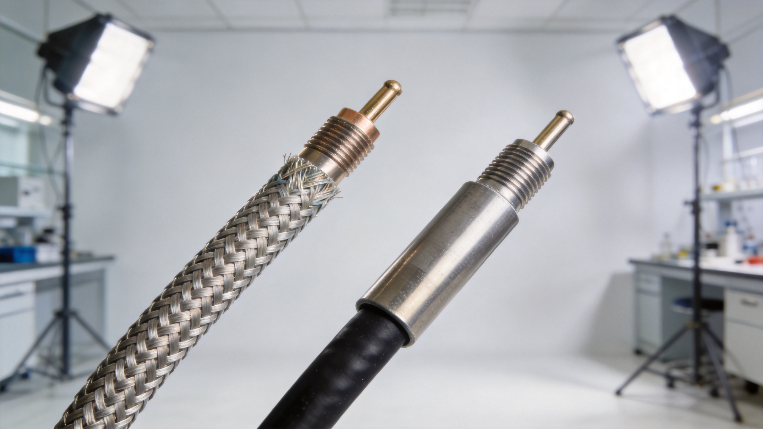
Worldpeak's product line for 50 Ω precision applications includes the Worldpeak RG196 50-Ohm Coaxial Cable, a semi-rigid RG RF cable with full engineering data suited to OEM design-in procurement where component approval processes require complete parameter documentation. For medical device manufacturers, defense integrators, and laboratory instrument OEMs, per-lot electrical documentation reduces incoming inspection overhead and simplifies traceability requirements.
Custom-length assemblies are available across connector interface families including SMA, N-type, BNC, and TNC, letting procurement teams to specify the exact routing length rather than adapting catalog dimensions to fit. Industry segments served include:
- Telecom infrastructure: 50 Ω semi-rigid and flexible assemblies for base station internal cabling; 75 Ω RG-6 and RG-6 U cables for DAS distribution at CATV frequencies.
- Defense and aerospace: Semi-rigid assemblies for radar, EW modules, and phased array feeds requiring phase stability under vibration and temperature cycling.
- Medical devices: Low-loss semi-rigid assemblies with RoHS and REACH material compliance documentation for imaging and therapy system integration.
- Laboratory and test: Phase-stable semi-rigid assemblies for VNA calibration paths and measurement references where cable phase drift affects measurement accuracy.
- Industrial automation and railway: Ruggedized flexible assemblies for wireless sensor networks and trackside communication equipment in high-vibration and chemically active environments.
If your primary constraint is frequency headroom and shielding effectiveness, semi-rigid rg rf cable is the appropriate grade regardless of unit cost. If your primary constraint is installation flexibility and long-run distribution loss for CATV or satellite signals, the 75 Ω flexible rg rf cable grades — RG-6, RG-6 U, and RG-179 cable — provide the right combination of attenuation performance and mechanical handling. The selection becomes straightforward once the checklist above confirms which constraints are active for your application.





