 EN
EN

Semi-Rigid Coaxial Cable Assembly: Uses and Design
As an RF systems engineer who has designed signal distribution systems across instrumentation, defense, and base station applications, I have found that the choice of cable assembly often determines whether the rest of the RF chain performs to specification—or quietly degrades it. The semi rigid coaxial cable assembly occupies a specific position: it is not the most flexible, but that is precisely where its value lies.
Before selecting a semi rigid coaxial cable assembly for any application, ask yourself: does your routing require the cable to hold a precise formed shape under thermal cycling, vibration, or repeated use? If the answer is yes, understanding the core electrical and mechanical specifications is the only way to make an informed choice.
Structure and Materials: What Separates Semi-Rigid From Flexible Cable
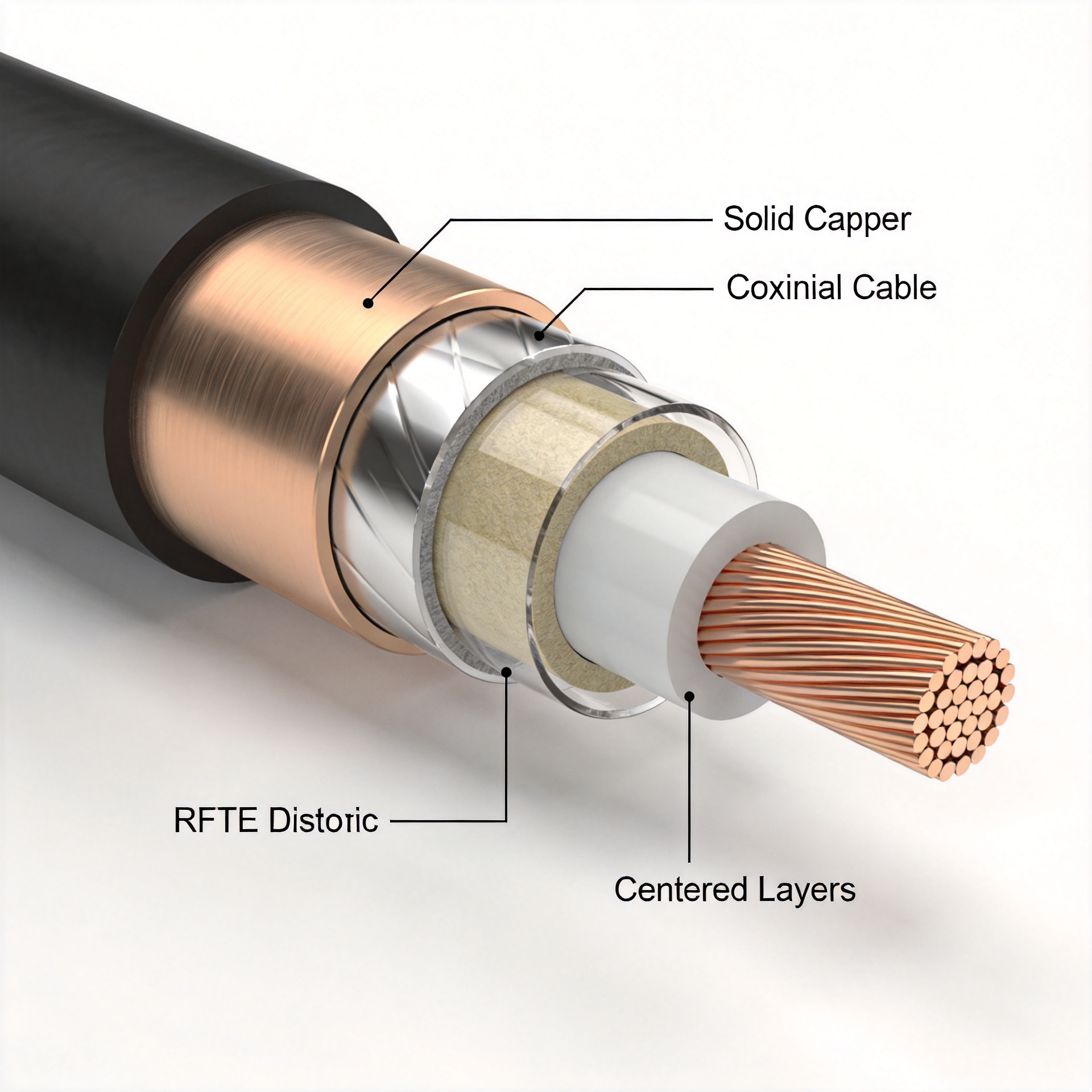
A semi rigid coaxial cable assembly consists of three main components: a solid metal outer conductor (typically copper, stainless steel, or tinned copper), a solid PTFE dielectric core, and a center conductor. Unlike braided flexible cables such as rg223 or rg214, the outer conductor in a semi-rigid design is a continuous drawn tube—not a braid. This construction produces the cable's defining characteristics: high shielding effectiveness, dimensional stability, and consistent impedance along the full cable length.
The solid outer conductor provides shielding attenuation typically exceeding 90 dB across the operating frequency range, which is substantially better than double-shielded flexible cables of the same size. For applications where signal integrity and a low system noise floor cannot be compromised—radar front ends, phase-matched antenna feed networks, precision test setups—this shielding level is difficult to match with flexible alternatives.
Impedance and Attenuation: The Electrical Specifications That Drive Selection
Semi-rigid coaxial cables are manufactured to standard characteristic impedances of 50Ω and 75Ω, with 50Ω being the dominant choice for RF and microwave signal transmission. The 75Ω variant is used in video distribution and cable television infrastructure. If your primary constraint is system impedance compatibility, this distinction should carry the most weight in your selection—in most RF engineering and wireless communication applications, 50Ω is the design baseline.
Attenuation varies with cable outer diameter and frequency:
- .086-inch type cables (RG405 class) offer approximately 0.22–0.38 dB/m at 1 GHz, depending on conductor material and dielectric quality.
- The .141-inch semi-rigid type is rated at 50Ω with an upper frequency limit reaching up to 36 GHz and maximum power handling of approximately 450 W at 1 GHz.
- Stainless steel outer conductor variants trade some conductivity for mechanical robustness—useful for high-vibration or chemically aggressive environments where a copper outer conductor would corrode or deform under stress.
Each doubling of frequency increases attenuation by roughly 1.4 to 1.8 times in most solid-dielectric coaxial cables. That is a working approximation, not a number to put directly in a link budget without measuring your specific assembly at operating temperature and actual routing geometry.
Phase Stability and Shielding Under Thermal Stress
The solid outer conductor in a semi rigid coaxial cable assembly provides dimensional stability under temperature changes, which translates directly to phase stability. In phased array antenna feeds, calibration setups, and any system where electrical length consistency across multiple cables matters, the PTFE-plus-solid-conductor construction holds a more repeatable phase response over a temperature swing than a braided-shield design of similar size.
Early in my experience with semi-rigid coaxial cable, I optimized for lowest insertion loss per meter. The blind spot was minimum bend radius, which set a separate limit that the lowest-loss cable could not overcome inside a tightly packaged instrument chassis. Both parameters need to be checked before finalizing a specification—neither can be traded away for the other without knowing the full routing geometry.
Cable Type Comparison: Semi-Rigid vs. RG223 or RG214
Not all coaxial cable assembly requirements call for semi-rigid construction:
- RG223 (double-shielded flexible coax) works well when repeated flexing, connector mating cycles, or field routing without pre-formed bends is required.
- RG214 (silver-plated double-shielded flexible cable) steps up shielding and conductor quality over RG223, and is often specified for defense, laboratory, and instrumentation applications at moderate frequencies.
- Semi-rigid is the right choice when the cable will be formed to a fixed shape, when shielding above 90 dB is required, or when phase-matched assembly length consistency must be maintained across a production batch.
For a front-panel cable assembly on a field-serviceable instrument, I once chose flexible cable over semi-rigid to allow repeated connector mating during calibration. The trade-off was approximately 0.3 dB higher insertion loss per meter at 18 GHz, but preventing connector body stress during panel swaps justified that decision. That kind of trade-off logic belongs in the specification stage, not in a commissioning conversation.
Bend Radius Requirements and Installation Constraints
The minimum bend radius of a semi rigid coaxial cable assembly is a hard mechanical constraint enforced by the outer conductor's solid wall structure. Exceeding it causes permanent outer conductor deformation, introducing an impedance discontinuity at the bend point that elevates VSWR at higher frequencies.
Practical reference values:
- .086-inch semi-rigid cable (RG405 class): minimum inside bend radius of approximately 0.05–0.12 inches, depending on outer conductor material and tooling. Copper allows tighter forming; stainless steel requires larger radii.
- Flexible coaxial types (RG223 and RG214): minimum bend radius of 5 to 12 times the cable outer diameter.
- Hand-formable .086-inch replacements: minimum bend radius of approximately 6 mm—useful when tooled forming is not available.
I once specified a semi rigid coaxial cable assembly for a cable harness with a tight 90-degree routing turn, without verifying the minimum bend radius against the chassis geometry first. Micro-cracking in the outer conductor at the bend required a full cable replacement after six months of vibration in service. Checking bend radius against the routing path before fabrication costs far less than replacing a finished assembly after system integration.
Connector Compatibility: SMA 905 and Interface Selection
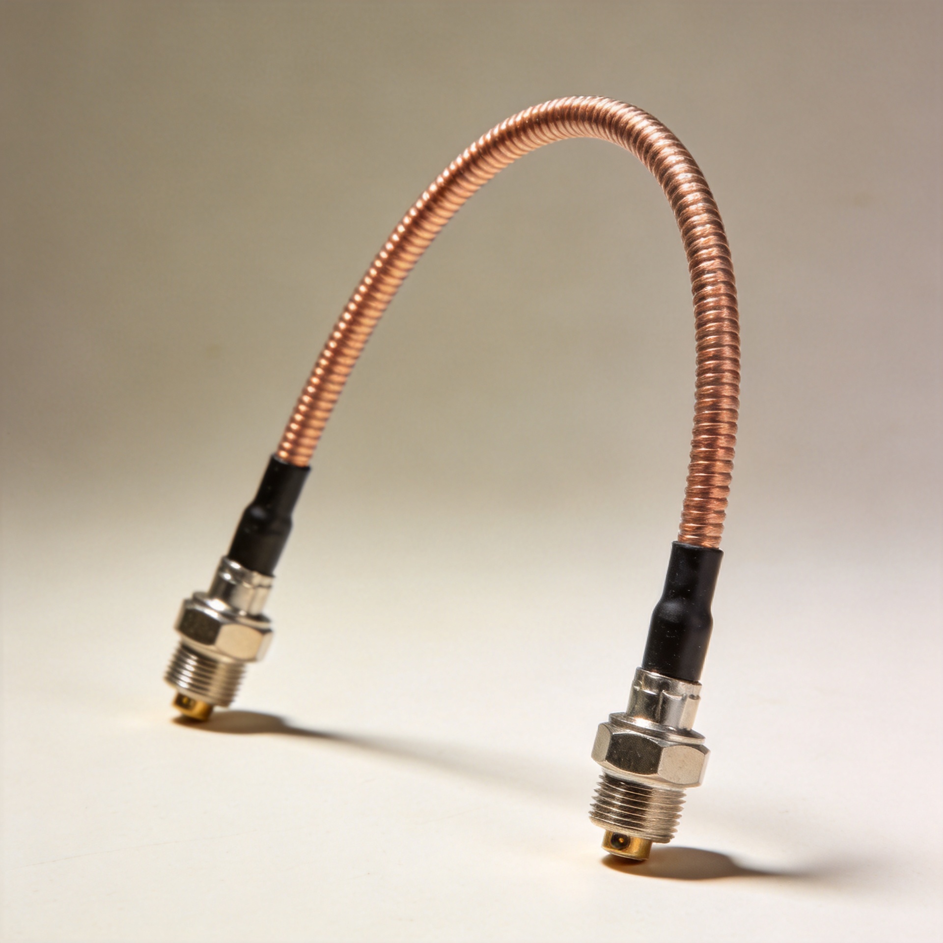
A semi rigid coaxial cable assembly is only as good as its connector termination. The most widely used interface for this cable class is the SMA family, including the sma 905 configuration—a precision variant suited to low VSWR and repeatable electrical performance in phase-critical measurement chains and applications with many mating cycles.
When specifying connector interfaces for semi-rigid assemblies, confirm the following at the procurement stage:
- Connector body material and plating (gold-plated contacts for lowest contact resistance; stainless steel body for corrosion resistance)
- Frequency rating relative to the assembly's operating band
- Gender and orientation (straight vs. right angle) for each end
- MIL-specification alignment if the application requires traceable documentation
Worldpeak RF cable assemblies are pre-tested with swept insertion loss and VSWR measurement before shipment, providing incoming inspection data for buyers specifying assemblies for medical, aerospace, or defense integration.
Summary: Selecting the Right Semi-Rigid Coaxial Cable Assembly
Specifying a semi rigid coaxial cable assembly correctly is not a single-parameter decision. Impedance, attenuation, shielding, bend radius, phase stability, connector interface, and operating environment all interact. Start with impedance (50Ω for RF/microwave), evaluate attenuation against your frequency band and link budget, and confirm that the cable's minimum bend radius is compatible with your routing geometry before releasing the specification to fabrication.
For applications where phase stability and shielding above 90 dB are the priority, a well-specified semi rigid coaxial cable assembly will consistently outperform flexible alternatives—provided the routing and installation constraints are respected throughout the product's service life.





