 EN
EN

Semi-Rigid Coaxial Cable: Specs and Precision RF Uses
As an RF systems engineer who has designed signal chains for laboratory measurement setups and phased array antenna systems, I have found that semi rigid RF cable selection decisions are often made too quickly. Engineers specify the lowest-loss option, order it, and discover the constraint they missed only after the cable is routed and terminated. The parameter they optimized for is fine. The parameter they forgot (bend radius, frequency headroom, or impedance tolerance under temperature) determines whether the assembly passes or gets rebuilt.
This article unpacks the key specifications that govern semi rigid coax selection and explains how to apply them in real procurement and design decisions.
What Makes a Semi-Rigid RF Cable Different
Unlike flexible coaxial cable with a braided or spiral-wound outer conductor, semi rigid RF cable uses a continuous solid outer conductor, typically drawn from copper or stainless steel. This construction produces three properties that flexible cable cannot match:
- Superior shielding effectiveness: The solid outer conductor provides near-complete EMI isolation, making semi rigid coax the preferred choice for circuits where external interference or signal leakage would compromise system performance.
- Phase stability: Electrical length remains consistent under bending and temperature variation. That consistency is critical for phased array antennas, beamforming networks, and differential measurement setups where phase imbalance degrades system performance.
- Low attenuation at high frequencies: The geometry of the solid outer conductor and precision-controlled dielectric maintain predictable insertion loss up to millimeter-wave frequencies.
The trade-off is mechanical rigidity. Semi rigid sma cable and other terminated assemblies are formed to shape before installation and cannot be re-routed without risking outer conductor damage. This constraint drives most of the practical decisions below.
Core Specifications to Evaluate
Characteristic Impedance: 50 Ω Versus 75 Ω
If your application is RF or microwave (radar, test instrumentation, wireless communications, medical imaging), the answer is 50 Ω. This is not a default; it is an engineered compromise that minimizes insertion loss for a solid dielectric cable while maintaining reasonable power handling. The 50 Ω standard dominates because the entire RF connector ecosystem—SMA, N-type, BNC in RF-grade versions, and their semi-rigid cable mates—is built around it.
75 Ω semi rigid RF cable exists for video and CATV distribution where the impedance standard matches source and load equipment. If you are sourcing semi rigid coax for an RF system and the datasheet says 75 Ω, you are looking at the wrong product family. Impedance mismatch loss at every interface will degrade link margin in ways difficult to diagnose without a careful VSWR sweep.
Outer Diameter and Frequency Limit
Industry-standard outer diameters for semi rigid RF cable run from 0.020 inches through 0.250 inches. The four most commonly specified sizes for system-level work are:
| OD (inches) | Typical Frequency Limit | Minimum Bend Radius (approx.) | Primary Use |
|---|---|---|---|
| 0.047" | Up to 65 GHz | ~2.4 mm | Compact RF modules, MMIC interconnects |
| 0.086" | Up to 40 GHz | ~4.4 mm | Test equipment, instrument chassis, general precision RF |
| 0.141" | Up to 18–26 GHz | ~7.1 mm | Defense, phased arrays, lab setups with wider routing paths |
| 0.250" | Up to 12–18 GHz | ~12.7 mm | High-power applications, military, industrial RF systems |
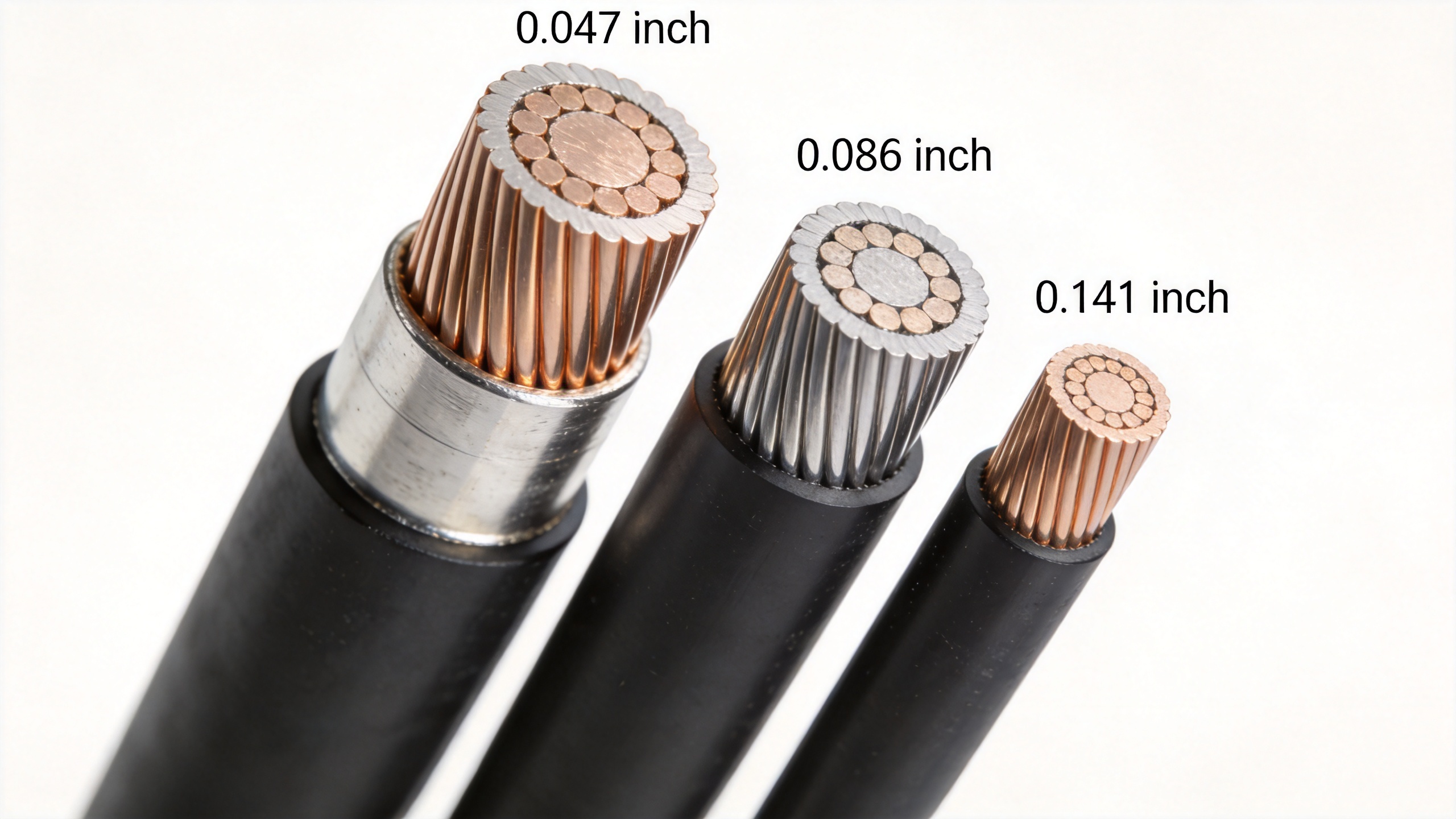
The relationship between OD and frequency limit follows directly from cable geometry physics. Larger outer conductors support higher-order propagation modes at lower frequencies, setting the upper frequency limit. When specifying a semi rigid sma cable assembly, confirm the OD and verify the frequency limit is above your operating band with meaningful margin.
Attenuation
Attenuation in semi rigid coax is dominated by conductor loss at lower frequencies and dielectric loss at higher frequencies. Typical insertion loss for a 0.086" cable runs from roughly 0.5 dB/foot at 1 GHz to over 2 dB/foot at 20 GHz. Ask yourself: how many links does your signal chain include? If the answer is more than two or three cable segments, attenuation accumulation becomes a real link budget concern—actually, it is often the first place engineers underestimate their loss budget at high frequencies.
For phase-sensitive systems, the critical figure is phase change with temperature rather than raw attenuation. Assemblies for phased arrays or beamforming networks should be specified for phase stability across the operating temperature range, not just insertion loss at room temperature.
Outer Conductor Material: Copper Versus Stainless Steel
Standard semi rigid RF cable uses a copper outer conductor. Copper provides the lowest resistive loss and is the right choice for most laboratory and instrument chassis applications in controlled environments.
Stainless steel outer conductor versions, such as the SR-086-SS304 from Worldpeak, are specified where corrosion resistance matters: coastal installations, military deployments, industrial RF systems exposed to humidity and salt, or medical equipment that undergoes repeated cleaning cycles. The trade-off is slightly higher insertion loss compared to copper, but in corrosion-sensitive applications the reliability benefit outweighs the loss penalty.
Bend Radius: The Constraint That Overrides Everything Else
Early in my experience with semi rigid coaxial cable, I optimized for lowest insertion loss per meter. The blind spot was minimum bend radius, which set an independent limit the lowest-loss cable couldn't overcome in a tightly packaged instrument chassis. I learned this the hard way.
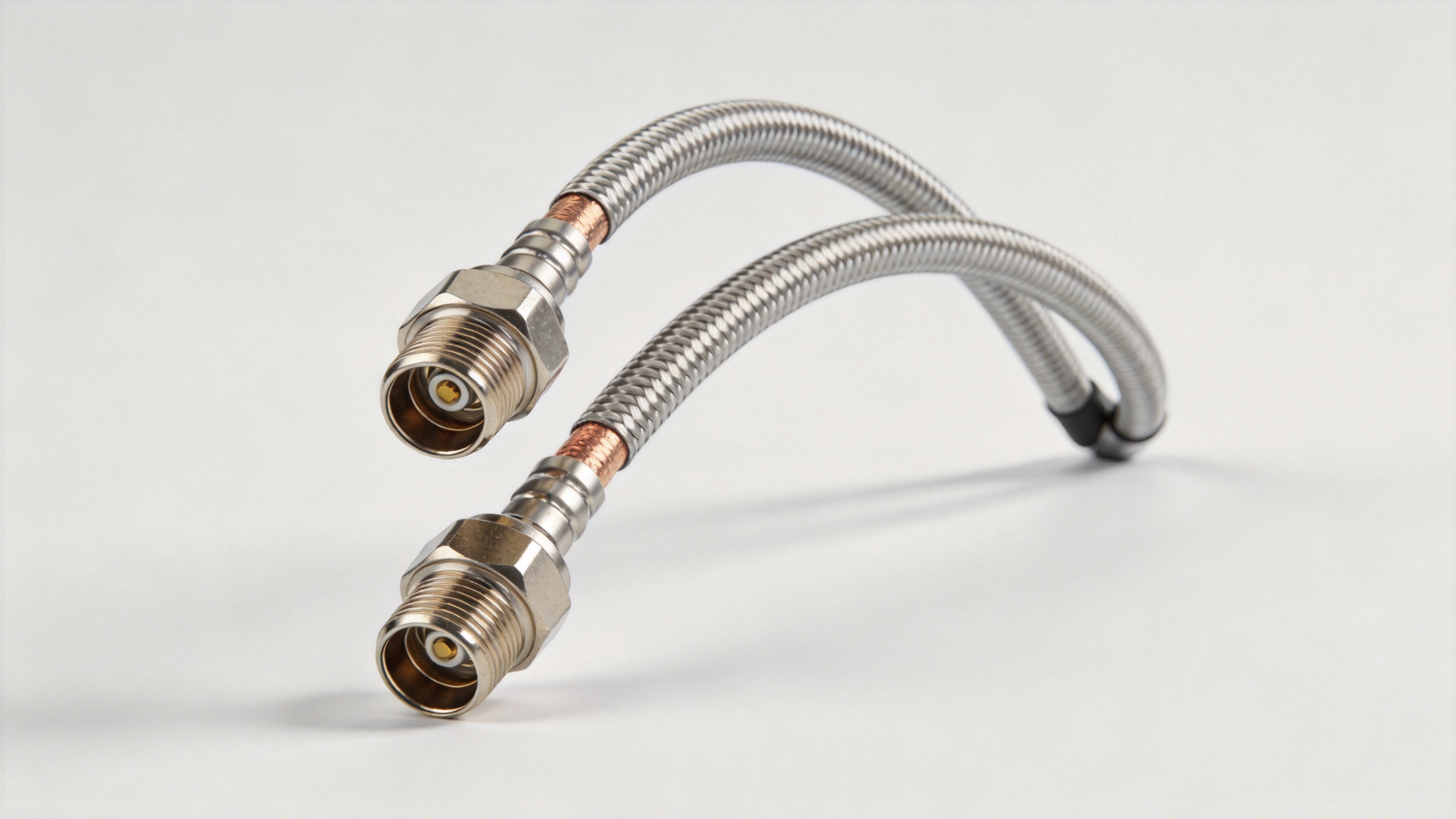
The minimum bend radius is not a guideline; it is a hard limit. Before choosing between semi-rigid cable sizes for your design, ask yourself: what is the tightest turn your routing geometry requires? If the answer is smaller than the minimum bend radius for your chosen OD, you have two options: select a smaller OD cable or redesign the routing geometry. There is no third option that preserves the cable's integrity.
Exceeding the minimum bend radius causes micro-cracks or flattening in the outer conductor. These defects create impedance discontinuities that may not appear in DC continuity checks and may not cause immediate failure at low frequencies, but will degrade VSWR and increase insertion loss as frequency rises—often developing into measurable failures after months of vibration or thermal cycling.
For sma semi rigid cable assemblies, bending is done once using a proper bending tool. Attempting to hand-form a semi-rigid assembly without tooling, or re-bending a formed assembly, risks the outer conductor integrity at the bend point.
Precision RF Applications Where Semi-Rigid Cable Is Required
Phase stability, shielding effectiveness, and predictable loss behavior make semi rigid coax the practical choice in several application classes where flexible cable alternatives fall short:
- Phased array and beamforming antenna systems: Phase-matched cable sets connect each array element to the beamformer. Electrical length variation between cables produces beam pointing errors that no post-installation calibration can fully compensate.
- RF and microwave test instruments: VNAs, spectrum analyzers, and signal generators use internal semi rigid assemblies because their electrical length must be stable enough to remain within the instrument's calibration tolerance across its operating temperature range.
- Radar and EW systems: In-box routing between modules must maintain phase coherence and electromagnetic isolation between signal paths. Flexible cable braid shielding effectiveness is typically insufficient for these requirements.
- Medical imaging RF front-ends: MRI and ultrasound systems require precisely characterized, low-loss cable assemblies with predictable phase behavior across the instrument's frequency range.
Sourcing Considerations for Procurement Teams
When evaluating semi rigid RF cable suppliers, electrical test documentation should be near the top of the qualification checklist. Each assembly should come with swept insertion loss and VSWR data measured against the actual assembly, not a batch sample—verifying compliance before installation and providing the baseline for future maintenance comparisons.
If your application involves phase-matched sets—for antenna arrays, interferometers, or balanced measurement networks—confirm that the supplier provides per-assembly electrical length verification. Phase-matched procurement upstream prevents the far more expensive problem of calibration iteration during system integration.
For procurement teams sourcing 50-ohm coaxial cable assemblies for RF system integration, the Worldpeak RG196 50-Ohm Coaxial Cable provides a reference point for specification review and selection guidance within the Worldpeak product range.
To summarize: semi rigid RF cable selection is a multi-constraint problem. Frequency limit and attenuation are the parameters most engineers start with. Bend radius, outer conductor material, and phase stability are the constraints that determine whether the optimized loss specification is achievable in your physical routing geometry and operating environment. Verify all of them before finalizing a specification.





