 EN
EN

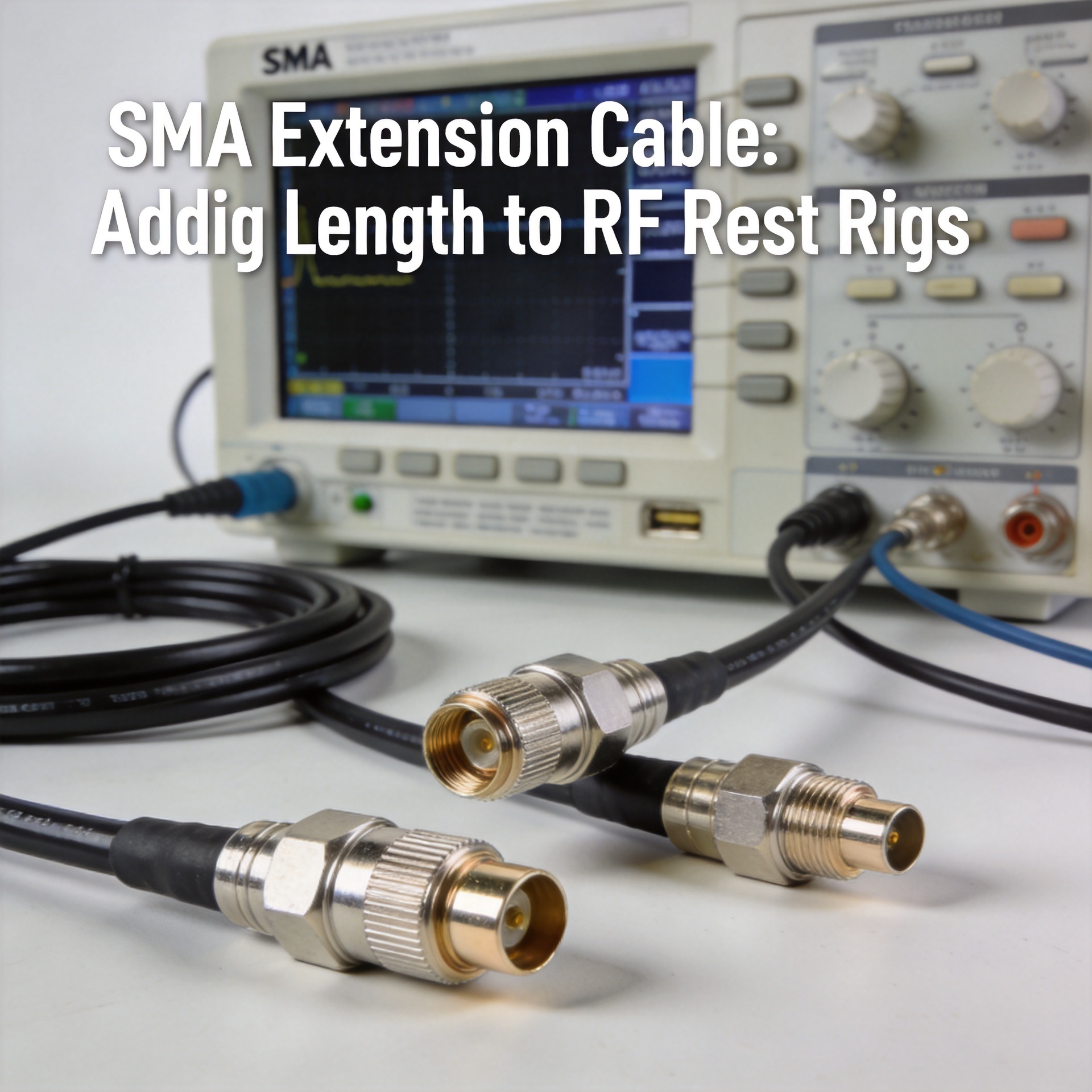
SMA Extension Cable: Adding Length to RF Test Rigs
In a calibrated test environment, I've found that an sma adapter cable with slightly worn plating can shift my measurement baseline by enough to invalidate results. That observation, repeated across enough bench setups, changed how I think about extending RF signal paths: the question isn't just "how long do I need?" but "what does this extension cost me in frequency headroom, power margin, and phase consistency?" Getting those answers right before you build a test rig is the difference between results you can defend and results you have to recheck.
SMA connectors appear in virtually every RF test environment. Wi-Fi adapters, cellular measurement tools, GPS signal simulators, vector network analyzers, and spectrum analyzers all use SMA or SMA-derived interfaces because the connector is compact, mechanically stable under repeated mating, and capable of supporting frequencies from DC to 18 GHz. Selecting the right sma adapter cable for a test rig extension is one of the most common and most consequential interconnect decisions an RF engineer makes.
SMA Variants: Standard, RP-SMA, Right-Angle, and Bulkhead
Before selecting an sma adapter cable for a test rig, you need to identify which variant you're working with. Two connectors that look identical on the outside can be electrically incompatible.
Standard SMA uses a 1/4-36 UNS threaded coupling with the center pin on the male connector and a corresponding socket on the female. This is the dominant interface on RF test equipment, signal generators, power dividers, and laboratory cable assemblies.
RP-SMA (Reverse Polarity SMA) retains the identical external thread pattern of standard SMA, 1/4-36 UNS, but reverses the inner contact geometry: the RP-SMA male body carries a receptacle (hole), while the female carries the pin. This reversal was introduced to prevent mixing commercial wireless hardware with standard RF test equipment. The external appearance is so similar that misidentification on a busy bench is common, and the result is a connector pair that threads together smoothly but conducts no signal.
Right-angle SMA connectors route the signal path through a 90-degree bend, enabling cable exits in constrained instrument panels or chassis corners. The angle transition introduces a slight impedance perturbation that is typically negligible below 6 GHz, but worth verifying by sweep if the test demands high return-loss repeatability above that range.
Bulkhead SMA connectors mount through panel cutouts, allowing the RF signal to cross a chassis boundary. They are common in test fixture designs where the device under test is inside a shielded enclosure and the measurement instruments are outside. A sma connector adapter in bulkhead form is often the first component selected when building an RF fixture wall.

Frequency Range and Power Handling
Standard SMA connectors are rated from DC to 18 GHz. Precision versions extend the usable range to 26.5 GHz or, in laboratory-grade assemblies, up to 34 GHz. The frequency ceiling matters: every additional connector in a signal chain introduces a small reflection, and those reflections interact constructively at frequencies related to connector body dimensions. Above the rated cutoff, this interaction becomes unpredictable.
Roughly speaking, each sma connector adapter in a chain adds somewhere in the range of 0.1 to 0.3 dB of insertion loss at 6 GHz. That is a ballpark estimate, not a number to put in a link budget without measuring your specific assembly. At 18 GHz, the same adapter may contribute 0.3 to 0.5 dB, depending on connector grade and contact condition. When you add an extension cable, you are adding both the cable loss and two additional mating interfaces at each end.
Power handling for SMA is rated at 75 W at 10 GHz at 25°C. In test applications, signal levels rarely approach this limit. However, if the sma adapter cable will carry amplified signals in a production test environment, thermal derating applies at elevated ambient temperature. If the extension will be used above 40°C ambient, verify the derated power ceiling against your signal source output before finalizing the assembly specification.
Assembly Options: Crimp, Solder, and PCB Termination
Extension cable assemblies come with three standard termination approaches, each with different performance and repairability trade-offs.
Crimp termination uses a mechanical die to compress the connector body around the cable outer conductor. It produces consistent results when the correct die and cable combination are used, and the compact assembly suits dense test fixtures. A crimped sma adapter cannot be reworked; if it fails, the full assembly is replaced.
Solder termination solders both the center and outer conductors to the connector body. When done correctly, solder joints provide excellent electrical continuity and can be inspected visually. This approach is preferred in test environments where the operator may need to modify or extend cables on-site.
PCB mount SMA connectors terminate directly to a printed circuit board via edge-launch or vertical-mount configurations. These are relevant when extending signals to or from a test board inside a fixture rather than to a standalone cable run.
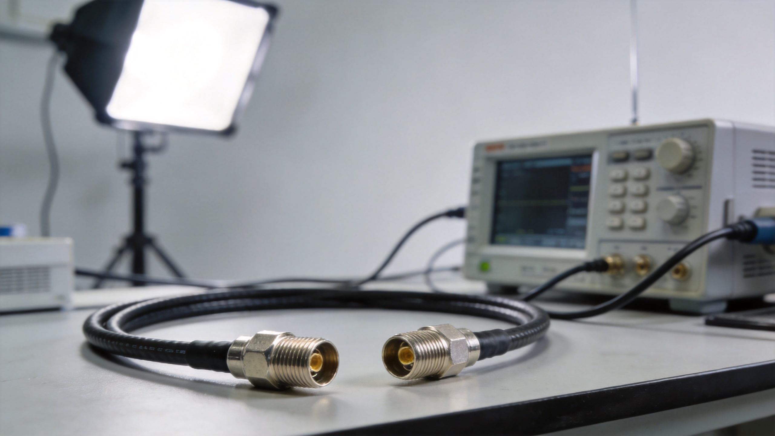
The SMA vs. RP-SMA Confusion
I expected that after years of bench work, the SMA versus RP-SMA mistake would become easy to catch. What actually happens is that the mistake occurs most often under time pressure, when connectors are taken from a shared parts bin without close inspection.
The external threads of an SMA and RP-SMA connector mate without resistance because they share the same 1/4-36 UNS thread. The connection feels complete and may feel mechanically secure. But no RF signal is transferred because the inner contact geometries are reversed. The result shows up as near-total signal loss on the analyzer, or more dangerously, as a partial connection where center contact wear creates an intermittent, frequency-dependent insertion anomaly.
The practical countermeasure: establish a physical separation in your parts storage between SMA and RP-SMA components, and confirm interface type visually before any connection. When ordering an sma to bnc adapter or any mixed-interface assembly, request explicit labeling of polarity type on both ends of the assembly documentation.
Selecting the Right SMA Extension Cable for a Test Rig
For most laboratory bench extension applications, a flexible low-loss sma adapter cable with SMA male connectors on both ends is the default starting point. The selection decision narrows around three parameters:
- Cable type: RG316 is suitable for low-power applications up to 6 GHz with minimal bend radius concern. For applications above 6 GHz or where phase stability under flexure matters, a semi-flexible assembly with a silver-coated copper outer conductor and PTFE dielectric is a better fit for the sma connector adapter chain.
- Length: Adding length adds insertion loss. For each additional meter of RG316 at 6 GHz, expect approximately 0.6 to 1.0 dB of additional attenuation. The exact figure depends on cable diameter and construction. If the measurement uncertainty budget cannot absorb this, a lower-loss cable type is the solution, not a shorter extension that doesn't reach the port.
- Connector grade: For calibration-plane measurements where the sma adapter cable is the first element after the VNA calibration kit, connector body grade and center pin condition directly affect the calibration residual. Using precision SMA connectors at those interfaces, even if standard connectors are used deeper in the chain, reduces measurement uncertainty without a complete upgrade.
Worldpeak produces SMA coaxial cable assemblies across a range of cable types, including RG316 and semi-flexible cores, with per-assembly electrical testing before shipment. For RF test rig extension requirements spanning DC to 18 GHz, a qualified sma adapter cable from a specialist supplier reduces the risk of measurement anomalies that trace back to inconsistent dielectric quality or contact condition variation between batches.
Summary
Extending a signal path in an RF test rig with an sma adapter introduces a predictable set of insertion loss, reflection, and phase effects. Keeping those effects within the measurement uncertainty budget requires matching the cable type and connector grade to the frequency and power requirements, confirming interface polarity before assembly, and treating the extension as part of the measurement chain rather than a passive interconnect.
The SMA connector's long history in RF work is a record of proven performance at reasonable cost. The decisions that determine whether an extension cable supports that track record are made during specification and selection, before the assembly is installed in the rig.





