EN
EN

sma-female-to-sma-female-lightning-arrester---dc---6-ghz, sma-female-to-sma-female-lightning-arrester---dc---6-ghz, /rf-lightning-arrester
EN
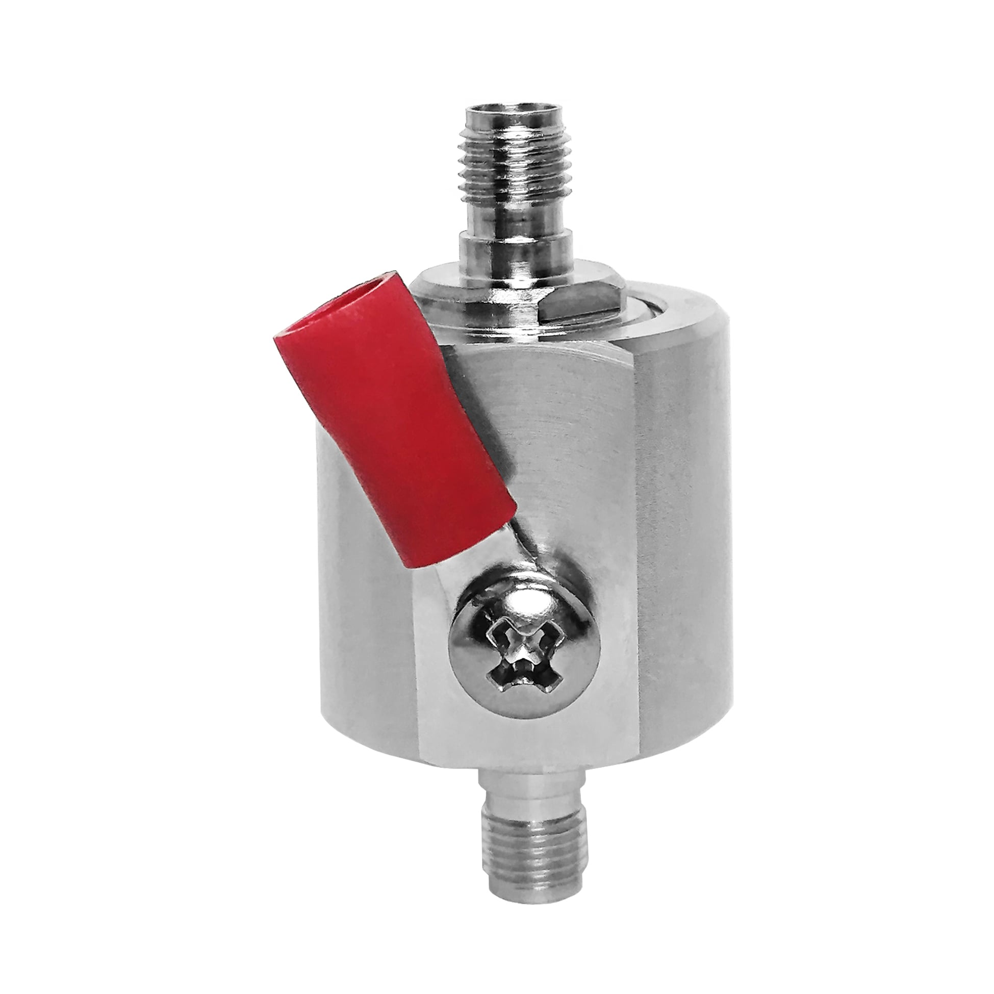
This SMA Female to SMA Female lightning arrester is a GDT based RF surge protector designed for DC - 6 GHz operation. It sits in the transmission line between the antenna and the radio equipment, diverting lightning-induced transients to ground before they reach the sensitive front end. The 50 ohm design holds insertion loss at 0.3 dB with a VSWR of 1.35 or better across the passband.
Request a Quote | Download Datasheet | Ask an Engineer
Product Overview
The SMA F-F lightning arrester is an inline GDT device for 50 ohm coaxial links operating from DC to 6 GHz. It uses a replaceable 90 V gas discharge tube and an M4 ring terminal to provide a route from a transient event to the site earth connection. In normal RF operation, the specified insertion loss is 0.3 dB.
This 6 GHz GDT RF surge protector for antenna lines combines female SMA interfaces with a serviceable protection element. The gas-discharge approach provides a low-capacitance path and has a triggering behavior distinct from diode-based protection. Selection should follow the cable arrangement, available earth connection, and final production configuration.
Protection Mechanism and Construction
Reference Technical Specifications
The following data are reference values for this product. Confirm the selected configuration against the final installation requirement before ordering or commissioning.
| Item | Value | Context |
| Connector arrangement | SMA Female to SMA Female | Inline RF connection |
| System impedance | 50 ohm | Reference line value |
| Operating range | DC to 6 GHz | Specified band |
| Insertion loss | 0.3 dB loss | Across stated band |
| VSWR | VSWR 1.35 | Maximum reference |
| Power handling | 100 W power | Reference CW condition |
| Protection element | 90 V GDT | Replaceable tube |
| Surge reference | 10 kA 8/20 us | Waveform basis |
| Earth terminal | M4 ring terminal | Ground-wire connection |
| Body material | Machined brass | Protective plating |
| Weight | Approx. 70 g | Reference mass |
| Typical application | Panel-mount equipment protection | Equipment context |
The values in this table should be verified against the final production configuration and the intended equipment arrangement.
Engineering Comparison
Applications
Installation and Grounding Notes
OEM and B2B Support
FAQ
Q: How often does the gas discharge tube need replacement?
A: Inspect the 90 V element after a major surge event. Replace it when leakage is present or when it does not pass the applicable hold-off test.
Q: Will this device affect a DC to 6 GHz signal?
A: The listed values are 0.3 dB loss and VSWR 1.35 across the stated band. Confirm suitability against the final RF assembly and operating requirement.
Q: Can this device be installed indoors?
A: Yes. The SMA F-F lightning arrester may be installed at an equipment-side cable position or at an entry point where an additional grounded stage is required. Review cable routing, panel access, connector engagement, earth-bar connection, and service clearance before commissioning. For panel-mount equipment protection, confirm the final production configuration and installation layout.