 EN
EN

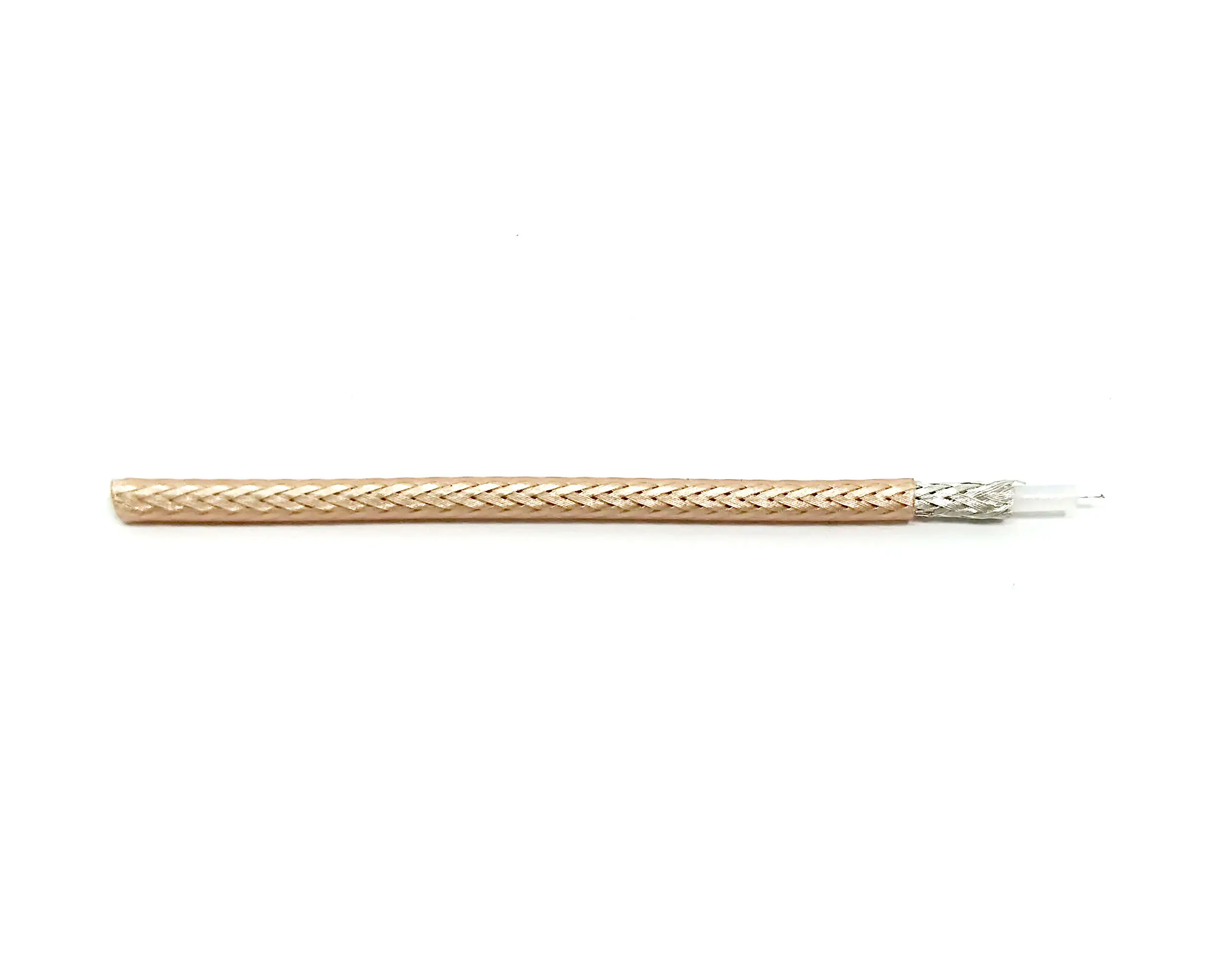
SMA Male to Female Connector: Extension and Applications
Here is a mistake that recurs on RF workbenches and integration floors. An engineer orders what appears to be a standard sma connector male to female adapter, installs it between a radio module and a panel-mount antenna port, then gets no signal — or a dramatically elevated VSWR. The culprit is typically an RP-SMA connector disguised as a standard SMA. They look identical: same thread pitch, same diameter. But their center contacts are gender-reversed. Understanding that difference is the starting point for any reliable SMA extension or adapter selection.
The SMA Connector Family: Four Variants You Will Encounter
The SMA interface operates from DC to 18 GHz (precision versions to 26.5 GHz), uses a 1/4-36 UNS threaded coupling, and carries a 50 Ω characteristic impedance. Four mechanical variants cover most applications:
- Straight SMA: the standard in-line configuration. The male plug has an inner thread with a center pin; the female jack has an outer thread with a center socket.
- Right-angle SMA: cable or board entry is perpendicular to the mating face. Impedance-controlled bend geometry is necessary near the 18 GHz upper limit to keep VSWR in range.
- Bulkhead SMA: secured to a panel with a rear nut. The female version creates a fixed feedthrough; this style is common in instrument chassis and enclosure wiring.
- RP-SMA: same 1/4-36 UNS thread as standard SMA, but with reversed center contact gender. The RP-SMA plug carries a center socket rather than a pin. This variant was developed for consumer Wi-Fi gear to discourage non-compliant antenna upgrades.
SMA vs RP-SMA: Why the Confusion Persists
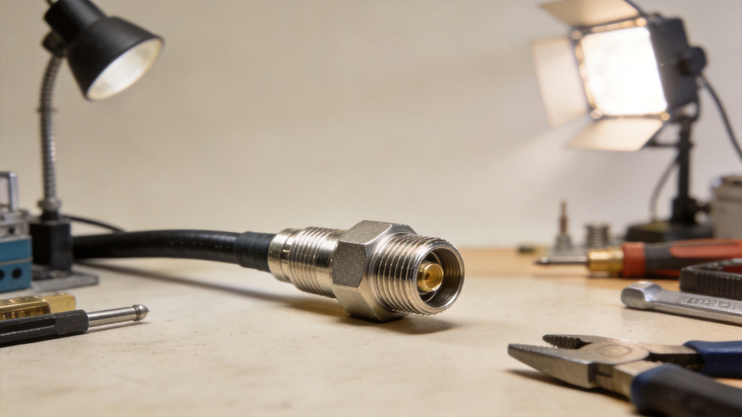
Consumer Wi-Fi routers, WLAN access points, and unlicensed-band radios use RP-SMA with near-universal consistency. GPS receivers, cellular modules, lab instruments, and professional RF systems use standard SMA. The external threads are physically identical — the only reliable check is the center contact. A standard SMA female has a center bore (a socket). An RP-SMA female has a center pin. If the fixed port on your device shows a pin, you need an RP-SMA male adapter, not a standard SMA male. That single visual inspection prevents the most common and costly specification error in SMA procurement.
Extension Cables: What an SMA Male to Female Cable Provides
A sma male to female cable is an extension assembly: SMA male plug at one end, SMA female jack at the other. The male end connects to a fixed female port on a module or instrument; the female end presents a mating point at a controlled distance away. Test setups use these cables routinely when an instrument's panel-mount female port needs to reach a device under test without introducing mechanical stress at the module's connector body.
Key selection parameters:
- Cable type: flexible RG-316 or LMR-series assemblies work well for most bench and installation applications. Semi-rigid cable (0.086", 0.141") is the choice for precision connections where mechanical stability is required.
- Frequency rating: GPS extensions need coverage to 1.6 GHz; 5 GHz Wi-Fi systems need at least 6 GHz; microwave test cables should stay flat to 18 GHz.
- Dielectric and body: PTFE dielectric provides stable performance across a wide temperature range (−65°C to +165°C). Stainless steel body options handle corrosive environments and outdoor installations better than brass.
Frequency Range, Power Handling, and Thread Specification
Standard SMA connectors carry a rating of 75 W CW at 10 GHz and 25°C. This exceeds what GPS receivers, Wi-Fi modules, and most cellular front-end components require. The constraint appears in high-power transmitter and feedline applications, where N-type (rated at 250 W at 18 GHz) or 7-16 DIN is the more appropriate interface. SMA is properly positioned in the low-power signal path, not at the transmitter output.
On the mechanical side: minimum mating cycle rating is 500 cycles. Coupling torque should fall in the range of 0.3–0.6 N·m (3–5 in-lb) for brass plugs and 0.8–1.1 N·m (7–10 in-lb) for stainless steel plugs. Under-torquing leads to intermittent contact; over-torquing can deform the center pin and introduce VSWR anomalies.
Cross-Type Adapters: SMA Female to BNC Male and N Female to SMA Male
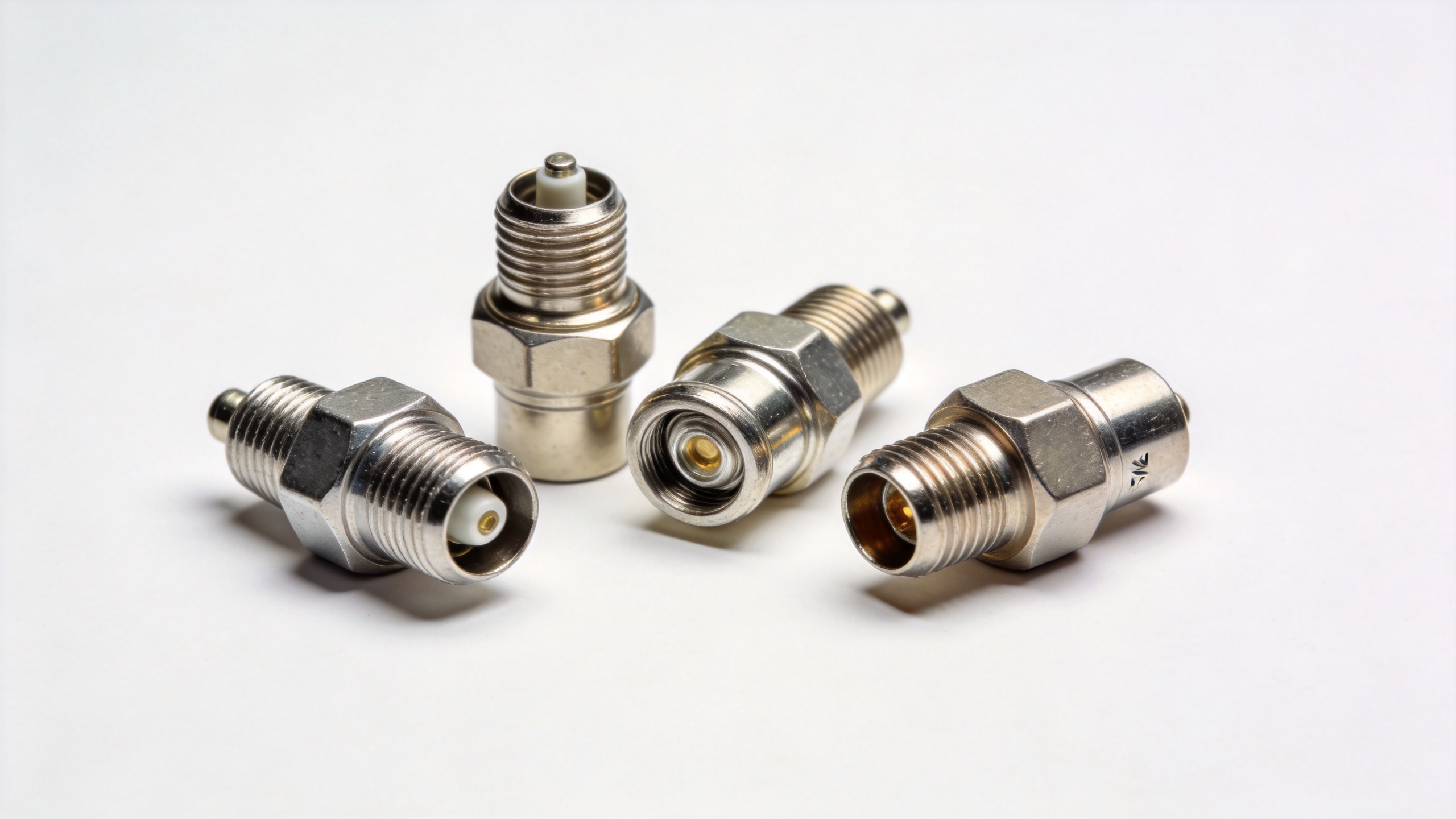
Signal paths often require bridging between connector families rather than extending within one. The two most common cross-type adapters in RF system assembly are sma female to bnc male and n female to sma male.
An sma female to bnc male adapter connects an SMA-terminated coax to a BNC-equipped instrument. BNC is a bayonet-lock design found on oscilloscopes, signal generators, and general test equipment rated to about 4 GHz. When an SMA signal path needs to reach a BNC port, this adapter eliminates the need to re-terminate the coax. Verify 50 Ω impedance (not 75 Ω, which is standard in video applications) and confirm the frequency rating covers the operating band.
An n female to sma male adapter scales a larger N-type female port — on an amplifier, power meter, or base station module — down to an SMA-terminated cable. N-type handles higher power at lower frequencies; SMA dominates at bench level and compact module interfaces. This adapter combination is common in test stations where a power amplifier's N-type output drives an SMA-input device under test.
Termination Options and Product Selection
For OEM assembly and PCB integration, three termination approaches cover most needs. Crimp is the most common method for flexible cable production; a consistent die selection is essential for repeatable electrical results. Solder termination works better for semi-rigid cable and precision 18 GHz connections, where direct bonding between the outer conductor and connector body reduces insertion loss. PCB end-launch mounts an SMA connector flush at the board edge with the center contact soldered to the RF trace; this requires controlled geometry to maintain impedance through the transition.
The RFX-Custom-01 Precision Machined RF Connector, SMA-Male to MCX-Female, 0–6 GHz, with SS304 Body is an example of a precision-machined adaptation connector that bridges an SMA interface to a compact MCX footprint for board-level integration. Worldpeak's portfolio spans SMA, N-type, BNC, TNC, MCX, and UHF interfaces — the UHF-BASIC-02 UHF (PL259) Female Connector covers legacy infrastructure integration needs alongside the SMA family.
Four Questions to Ask Before You Order
Before specifying any SMA male to female connector or adapter, four parameters are worth locking down:
- Standard SMA or RP-SMA? Inspect the fixed female port: a socket means standard SMA; a pin means RP-SMA.
- Frequency coverage? GPS (1.5 GHz), Wi-Fi (5.8 GHz), and microwave test (18 GHz) each call for a different assembly rating.
- Power level? SMA handles up to 75 W at 10 GHz. Higher-power transmit applications need N-type or 7-16 DIN at the feedline.
- Environment? Indoor bench adapters work fine with brass and gold plating. Outdoor or chemically aggressive environments call for stainless steel connector bodies and proper interface sealing.
Most field failures with SMA connectors trace back not to the interface design itself but to a polarity mismatch, an under-rated frequency assembly, or an incorrect torque at installation. A confirmed answer on each of these four points removes the most common specification errors from SMA male to female connector procurement.





