 EN
EN

7/16 DIN Connector Guide: High-Power RF Standard
2026/09/24
Choose a 7 16 connector for high-power RF: compare DIN and Type N, protect PIM margin, and apply field installation checks.
2026/09/10
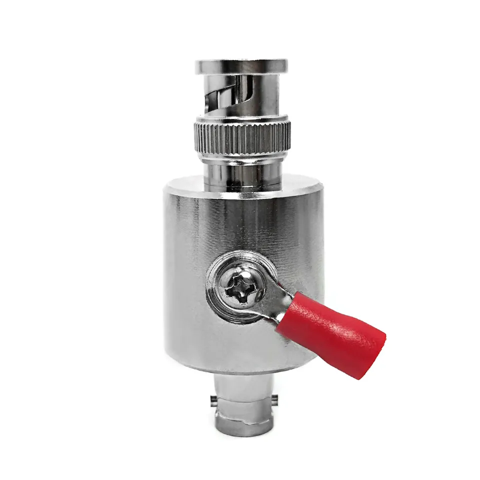
Coaxial interconnects are the backbone of radio frequency labs, video signal networks, and electronic test environments. While direct cable runs are ideal, real-world testing setups frequently require splitting signals, joining existing leads, changing connector genders, or bridging entirely different interface series. At the core of these tasks sits the versatile bnc adapter, a compact passive fitting designed to provide clean signal routing while preserving impedance stability across sub-4 GHz paths.
Choosing the right adapter configuration requires evaluating far more than just mechanical fit. Factors like signal attenuation from passive splitting, contact impedance mismatches between 50-ohm and 75-ohm lines, and maximum operating frequency limits directly dictate whether a measurement setup stays accurate. Understanding when to deploy specific adapter geometries protects sensitive instrumentation, keeps reflections low, and speeds up daily bench troubleshooting.
BNC hardware comes in several physical geometries, each designed to solve a specific signal routing or equipment interface challenge on the bench.
| Adapter Type | Interface Geometry | Typical Insertion Loss | Primary Industrial Application |
|---|---|---|---|
| BNC Tee | 1 Male to 2 Female (T-Shape) | ~3 dB Signal Split | Monitoring signals, reference clock distribution |
| BNC Barrel | Female to Female (Inline) | ~0.1 dB to 0.2 dB | Extending cable runs, panel bulkhead feedthroughs |
| BNC In-Line Adapter | Male-Male or Male-Female | ~0.05 dB to 0.1 dB | Changing port gender, protecting instrument ports |
| BNC to SMA Adapter | BNC Male/Female to SMA Female/Male | ~0.15 dB @ 3 GHz | Bridging lower-frequency gear to microwave modules |
Matching the specific geometry to the mechanical routing path avoids placing lateral strain on delicate front-panel equipment sockets.
A BNC tee allows a single signal path to split into two separate paths, or conversely, combines two incoming signals into a single port. Featuring a single male plug flanked by two female sockets, it sits directly on instrument input channels.
When using a passive tee to split a signal between an oscilloscope and a frequency counter, physics dictates a voltage drop. Passive signal division reduces the signal amplitude by approximately 3 dB at each output leg. For high-amplitude reference clocks or digital trigger pulses, this signal drop is usually negligible. However, for low-level RF power measurements or sensitive spectrum analysis, active distribution amplifiers should replace passive tees to prevent unwanted circuit loading.
Joining separate cable segments or altering connector orientation requires reliable inline fittings engineered to maintain tight 50-ohm characteristic impedance.
Bridging lower-frequency bench gear with microwave modules often requires connecting different connector series. The bnc to sma adapter links standard BNC equipment, common in sub-GHz test gear and video lines, to threaded SMA interfaces designed for high-frequency applications.
When deploying a bnc to sma adapter, the maximum operating frequency of the entire line becomes limited by the BNC interface, generally capping clean performance at 4 GHz for 50-ohm versions. Furthermore, engineers must verify impedance matching. Connecting a 75-ohm BNC adapter to a 50-ohm SMA line introduces an impedance discontinuity that generates a 14 dB return loss, reflecting significant RF power back toward the source.
In an RF calibration facility, technicians needed to route a 10 MHz atomic clock reference signal to four separate measurement instruments simultaneously.
Using a series of BNC tee fittings mounted directly to instrument inputs, the team built a daisy-chain distribution line. A frequency counter monitored signal stability at the final terminal node while three oscilloscopes tapped into the reference path. Because the master reference clock delivered ample output power, the 3 dB splitting drop across each tee remained well within the operating input thresholds of the receiving instruments, creating a cost-effective distribution harness without adding active amplifiers.
Achieving maximum service life and low VSWR from passive adapters requires proper handling discipline during daily bench operations:
Delivering consistent, low-loss interconnects requires high-precision CNC machining, high-purity alloy selection, and tight quality assurance processes. Microscopic variations in contact plating thickness or internal dielectric alignment directly impact return loss at gigahertz frequencies.
Worldpeak meets these strict industrial demands through automated manufacturing, precision contact plating, and complete RF characterization testing. Supplying a comprehensive range of bnc adapter configurations, precision BNC tee splitters, heavy-duty BNC barrel couplers, inline gender changers, and specialized bnc to sma adapter units, Worldpeak utilizes premium materials including gold-plated beryllium copper center contacts, machined brass bodies, and pure PTFE insulators.
Every Worldpeak adapter undergoes rigorous testing to guarantee VSWR ratings below 1.2:1 across designated operating bands. Whether equipping calibration laboratories, scaling broadcast infrastructure, or sourcing custom interconnect components, partnering with an established RF manufacturer like Worldpeak guarantees long-term transmission reliability across every link in your signal path.

2026/09/24
Choose a 7 16 connector for high-power RF: compare DIN and Type N, protect PIM margin, and apply field installation checks.

2026/09/24
Compare TNC connector types, specs and applications, including RP-TNC, bulkhead options, vibration performance and adapter selection.

2026/09/24
Understand MMCX connector basics, RF limits, and how to choose the right coaxial interface for compact systems.

2026/09/24
Understand RP-SMA connector polarity, mating rules, frequency checks, and OEM termination options for reliable RF builds.

2026/09/24
Choose the right bnc male connector for RF, CCTV and test systems with clear 50Ω vs 75Ω, type and installation guidance.

2026/09/24
Compare LMR400 specs, cable loss, uses, connectors and RG8/RG213 alternatives with a practical RF loss-budget method.