 EN
EN

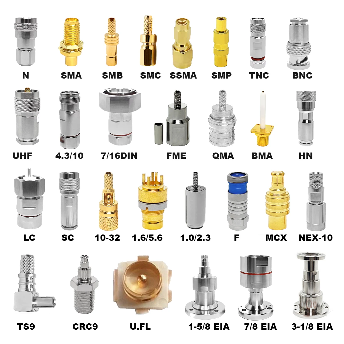
Coaxial transmission lines frequently require transitions across interface families, whether linking an RF bench generator to a device under test, adapting an antenna feeder, or interfacing modular subsystems inside a shielded enclosure. While mechanical thread compatibility is easily verified by eye, the primary engineering challenge centers on preserving signal integrity. A cable coax adapter serves as an inline transmission line section rather than a simple passive mechanical coupler. Deploying an unverified component can trigger severe signal reflections, standing waves, and phase distortion that compromise precision RF links.
Selecting an effective coax cable adapter requires evaluating three core variables: characteristic impedance, maximum operating frequency, and physical mounting geometry. Overlooking any of these parameters can convert a functional mechanical joint into an unexpected impedance mismatch.
Core Principles of Coaxial Transmission Line Transitions
Every coaxial transition acts as a localized segment of a distributed transmission line. The characteristic impedance is governed by the ratio of the outer conductor inner diameter to the center conductor outer diameter, combined with the relative permittivity of the internal dielectric material.
Whenever an inline cable coax adapter introduces a dimensional discontinuity or dielectric variance, an electrical reflection occurs. Connecting a 50 Ω transmission line directly to a 75 Ω termination generates an intrinsic reflection coefficient of 0.20, resulting in a baseline Voltage Standing Wave Ratio of 1.50:1 and a return loss of roughly 14 dB. In broadband digital communications or precision microwave links, such discontinuities produce pulse ringing, jitter, and elevated bit error rates. Preserving impedance uniformity across the entire transmission path prevents destructive phase cancellations and preserves system dynamic range.
Primary Interface Families and Electrical Boundaries
RF installations deploy distinct connector architectures tailored to specific frequency, power, and environmental envelopes. Selecting the appropriate cable coax adapter requires matching the mechanical interface family to the functional demands of the signal chain.
-
N-Type Interfaces: Robust threaded connectors engineered for harsh outdoor environments, antenna towers, and rugged industrial enclosures. N-type transitions deliver high power handling and reliable shielding from direct current up to 11 GHz or 18 GHz in precision configurations.
-
SMA Interfaces: Miniature threaded connectors widely favored across microwave modules, aerospace avionics, and high-density RF printed circuit boards. Rated typically up to 18 GHz or 26.5 GHz, SMA connections demand precise coupling torque to prevent contact galling and air gap reflections.
-
BNC Interfaces: Bayonet-style connectors designed for rapid connect-disconnect cycles in laboratory oscilloscopes, instrumentation, and legacy video distribution. BNC assemblies are manufactured in both 50 Ω and 75 Ω geometries, making dimensional verification critical.
-
F-Type Interfaces: Cost-effective threaded connectors prevalent in residential broadband, satellite feeds, and 75 Ω digital coaxial cable distribution networks.
Interface Family
Coupling Mechanism
Standard Impedance
Common Frequency Ceiling
Primary Applications
N-Type
Threaded (5/8-24 UNEF)
50 Ω / 75 Ω
DC to 11 GHz / 18 GHz
Base Stations, Antenna Feeders, Radar
SMA
Threaded (1/4-36 UNS)
50 Ω
DC to 18 GHz / 26.5 GHz
Microwave Subsystems, Avionics, Test Racks
BNC
Bayonet Lock
50 Ω / 75 Ω
DC to 4 GHz / 12 GHz
Laboratory Instruments, Broadcast Video
F-Type
Threaded (3/8-32 UNEF)
75 Ω
DC to 1 GHz / 3 GHz
CATV, Satellite Distribution, Audio Feeds
| Interface Family | Coupling Mechanism | Standard Impedance | Common Frequency Ceiling | Primary Applications |
|---|---|---|---|---|
| N-Type | Threaded (5/8-24 UNEF) | 50 Ω / 75 Ω | DC to 11 GHz / 18 GHz | Base Stations, Antenna Feeders, Radar |
| SMA | Threaded (1/4-36 UNS) | 50 Ω | DC to 18 GHz / 26.5 GHz | Microwave Subsystems, Avionics, Test Racks |
| BNC | Bayonet Lock | 50 Ω / 75 Ω | DC to 4 GHz / 12 GHz | Laboratory Instruments, Broadcast Video |
| F-Type | Threaded (3/8-32 UNEF) | 75 Ω | DC to 1 GHz / 3 GHz | CATV, Satellite Distribution, Audio Feeds |
Mechanical Form Factors and Enclosure Constraints
Mechanical clearance and thermal dissipation dictate physical adapter selection across modern equipment layouts.
Straight transitions provide the lowest insertion loss and highest frequency headroom. By maintaining a linear coaxial axis, internal discontinuities remain minimal. However, straight configurations demand adequate rear clearance to respect cable minimum bend radius specifications.
A coaxial cable 90 degree adapter addresses severe spatial limitations where cabling must route flush against a rack wall or chassis bulkhead. While a coaxial cable 90 degree adapter relieves mechanical strain on rigid and semi-rigid coaxial assemblies, the internal corner geometry introduces capacitive discontinuities. Premium designs utilize mitered internal corners or precision-radiused center conductors to maintain low VSWR at microwave frequencies.
Panel-mount and bulkhead transitions establish a permanent, hermetic, or shielded partition between internal circuitry and external field connections. These units absorb daily mating wear, preserving internal modular electronics from physical strain.
Comparing RF Systems and Digital Coaxial Cable Networks
A frequent failure point in mixed-signal installations involves confounding 50 Ω RF transmission lines with 75 Ω digital coaxial cable runs. While both architectures utilize concentric cylindrical conductors, their dielectric profiles and dimensional ratios serve contrasting engineering objectives.
A 50 Ω transmission line represents an optimal compromise between high-frequency power handling and dielectric breakdown voltage, making it the global standard for RF transmitters, wireless base stations, and test instrumentation. A matching 50 Ω cable coax adapter maintains uninterrupted shielding and minimal phase shift across wide test sweeps.
Conversely, a 75 Ω line minimizes signal attenuation per unit length, making it ideal for long-distance signal transport such as cable television, high-definition SDI video, and S/PDIF audio distribution over digital coaxial cable. Interfacing these differing systems requires calibrated minimum-loss matching pads or broadband RF transformers. Installing a standard 50 Ω coax cable adapter into a 75 Ω digital coaxial cable feed degrades return loss, causing packet loss and image ghosting.
Parameter
50 Ohm RF Coaxial Line
75 Ohm Digital Coaxial Cable
Primary Design Focus
Maximum Power Handling & Voltage Breakdown
Minimum Signal Attenuation per Foot
Core Applications
Transmitters, Test Benches, Microwave Links
Broadcast Video, CATV, Digital Audio (S/PDIF)
Standard Dielectric
Solid PTFE or Micro-porous PTFE
Foamed Polyethylene (FPE)
Velocity of Propagation
Typically 66% to 85%
Typically 80% to 88%
Mismatch Consequences
High reflected power, transmitter thermal trip
Bit error spikes, phase jitter, sync loss
| Parameter | 50 Ohm RF Coaxial Line | 75 Ohm Digital Coaxial Cable |
|---|---|---|
| Primary Design Focus | Maximum Power Handling & Voltage Breakdown | Minimum Signal Attenuation per Foot |
| Core Applications | Transmitters, Test Benches, Microwave Links | Broadcast Video, CATV, Digital Audio (S/PDIF) |
| Standard Dielectric | Solid PTFE or Micro-porous PTFE | Foamed Polyethylene (FPE) |
| Velocity of Propagation | Typically 66% to 85% | Typically 80% to 88% |
| Mismatch Consequences | High reflected power, transmitter thermal trip | Bit error spikes, phase jitter, sync loss |
High-Frequency Discontinuities in Angled Transitions
Routing signals through a coaxial cable 90 degree adapter introduces complex electromagnetic challenges that do not exist in straight transitions. At sharp 90-degree internal bends, the physical distance traveled by the electromagnetic field along the outer conductor differs significantly from the inner conductor path length. This structural asymmetry creates localized shunt capacitance and inductive peaking.
Standard utility-grade right-angle fittings use abrupt perpendicular pin joints that reflect substantial energy above 2 GHz. In contrast, precision-grade components incorporate mitered outer walls and custom dielectric undercut steps to tune out parasitic capacitance. When deploying a coaxial cable 90 degree adapter in wideband or microwave paths, validating return loss curves across the actual frequency spectrum is essential to prevent signal notch filters.
Practical Assembly Verification and Inspection Protocols
Deploying transitions into mission-critical systems requires disciplined incoming inspection and bench validation protocols:
-
Verify mating interface dimensions against MIL-STD-348 or IEC specifications using optical comparators to prevent pin protrusion damage.
-
Inspect internal PTFE or air dielectrics for surface contamination, machining burrs, or axial displacement.
-
Verify center conductor concentricity to ensure uniform contact retention force across repeated mating cycles.
-
Execute vector network analyzer sweep measurements across the rated frequency band to record return loss and insertion loss metrics.
-
Confirm that any coaxial cable 90 degree adapter deployed in the assembly satisfies the system VSWR ceiling across peak operational temperatures.
-
Document the complete transition part number, interface genders, characteristic impedance, and maximum frequency on system engineering schematics.
-
Establish a controlled coax cable adapter storage protocol in testing labs to prevent inadvertent cross-mating of visually identical 50 Ω and 75 Ω components.
Precision Manufacturing and OEM Capabilities with Worldpeak
Sustaining repeatable RF performance across enterprise supply chains requires tightly controlled manufacturing processes and rigorous lot testing. Worldpeak stands as a dedicated manufacturer and global supplier of high-precision RF connectors, adapters, and custom coaxial assemblies. Leveraging multi-axis CNC Swiss turning centers, Worldpeak achieves mechanical machining tolerances down to ±0.005 mm, ensuring that every cable coax adapter maintains exact concentricity and low contact resistance.
The engineering facilities at Worldpeak provide comprehensive OEM and ODM support, delivering both standard inter-series transitions and custom-engineered coaxial cable 90 degree adapter units rated up to 18 GHz and beyond. Every batch undergoes rigorous quality control, including 100% vector network analyzer sweep testing, plating thickness verification, and environmental salt-spray screening. Whether designing high-reliability aerospace test links or outfitting broadcast facilities with precision digital coaxial cable infrastructure, Worldpeak offers the production capacity, rapid prototyping, and international supply chain agility needed to keep mission-critical signals clean and repeatable.





