 EN
EN

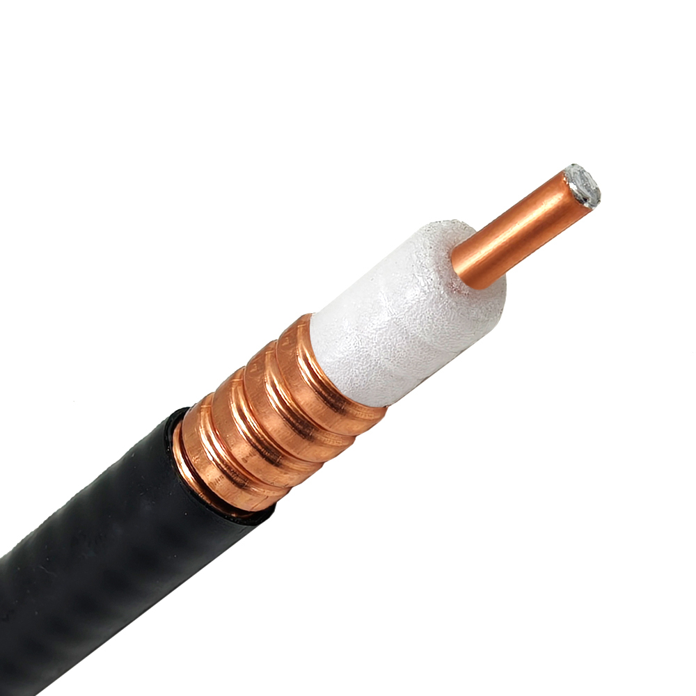
When designing base station jumpers, outdoor telecom runs, or distributed antenna system (DAS) networks, calculating RF loss at 900 MHz involves much more than measuring straight lines on an architectural blueprint. Every meter of transmission line acts as an active component in the system link budget. A small calculation mistake along a long vertical riser can quickly consume signal headroom and degrade overall coverage.
Getting accurate loss figures requires using the specific manufacturer datasheet for the exact product installed, converting attenuation figures into per-meter values, and adding every inline passive loss across the entire transmission path.
Extracting 900 MHz Attenuation Data from Datasheets
Manufacturer technical sheets typically express attenuation as decibels lost per 100 meters or 100 feet at specific frequency points. Calculating real-world path loss starts by determining the exact loss per meter at 900 MHz:
-
Convert Datasheet Attenuation: Divide the published 100-meter loss figure by 100 to establish the base loss per meter.
-
Calculate Physical Cable Attenuation: Multiply the base per-meter value by the total installed route length.
-
Add Inline Interface Losses: Factor in insertion loss from every mated connector pair, jumper transition, and lightning surge protector.
For example, if a heavy-duty cable feeder lists a loss of 4.0 dB per 100 meters at 900 MHz, the base attenuation works out to 0.04 dB per meter. A 60-meter installed run contributes 2.40 dB of signal loss from the line alone, before adding hardware connections or jumper leads.
Accounting for Installed Route Dimensions
Architectural floor plans rarely reflect true cable routing. Installation crews must account for vertical riser runs, cable tray turns, service loops, grounding point offsets, and equipment cabinet entry loops:
-
Include Service Loops: Always add approved slack loop allowances at antenna bases and equipment racks to facilitate future maintenance.
-
Verify Bend Radius: Over-tightening bends distorts the internal dielectric layer, creating impedance mismatches that increase signal reflection.
-
Avoid Generic Online Averages: Use the precise frequency attenuation curve provided by the supplier for the exact cable line installed.
Failing to account for extra routing length often leads to unexpected path attenuation during final system commissioning and VSWR sweep testing.
Factoring Jumpers, Adapters, and Extension Leads into the Budget
Transmission lines represent only one part of the overall link loss budget. A single well-installed connector introduces minimal attenuation, but combining multiple interconnects, jumper lines, and extension leads adds up rapidly across a multi-sector installation.
A flexible sma cable jumper provides necessary strain relief and tight bending inside compact equipment cabinets. However, high-frequency sma cable assemblies exhibit higher attenuation per meter than thick mainlines, meaning their usage should be limited to short internal connections rather than extended runs.
Similarly, adding a coax extension cable solves local reach issues during retrofits, but it introduces an extra transmission segment alongside two additional connector pairs. Every added junction must be recorded in the overall loss budget to prevent performance degradation.
Feeder Diameter versus Routing Tradeoffs
Choosing the proper line size involves balancing low signal loss against mechanical routing constraints. Larger outer conductors provide lower RF resistance and superior power handling, but they introduce physical installation challenges:
-
Compact Lines: Ideal for short cabinet jumpers or tight indoor pathways; easy to bend, but exhibits higher attenuation per meter.
-
Medium-Diameter Lines: Balances manageable routing and bend performance with moderate signal attenuation; suitable for indoor DAS branches.
-
Large Corrugated Feeders: Provides ultra-low attenuation across long vertical tower runs; demands heavy-duty support hangers and wide bend radii.
Power handling capacity must also be verified independently from attenuation limits. Operating temperature, ambient weather conditions, and high transmitter power levels affect line performance over extended service lifecycles.
Field Checklist for Acceptance Testing
-
Use Exact Attenuation Ratings: Confirm attenuation figures against the manufacturer datasheet at 900 MHz rather than generic chart approximations.
-
Standardize Measurement Units: Convert all physical run lengths and loop allowances into meters before calculating path loss.
-
Count Mated Connector Pairs: Calculate loss for every mated interface pair rather than counting individual connector bodies.
-
Weatherproof Outdoor Interfaces: Apply self-amalgamating tape or cold-shrink boots over all exterior junctions to prevent moisture ingress.
-
Partner with Certified Manufacturers: Work with established cable harness manufacturers who supply fully tested jumper assemblies with documented return loss test reports.
Streamlining RF Infrastructure with Precision Manufacturing
Building dependable wireless networks requires sourcing coaxial components and custom assemblies from suppliers who maintain strict manufacturing standards, high-grade plating, and reliable global distribution channels. Inconsistent dielectric dimensions or poor ferrule crimps degrade return loss and inflate path attenuation across 900 MHz networks.
Worldpeak supplies precision-engineered cable feeder lines, specialized sma cable leads, low-loss coax extension cable jumpers, and custom RF harness assemblies for telecom, industrial wireless, and broadcast infrastructure globally. Positioned among leading cable harness manufacturers, Worldpeak backs its RF products with automated production equipment, rigorous VSWR testing, and complete quality traceability.
Whether your next build demands bulk cable feeder spools, custom sma cable jumpers, or specialized coax extension cable assemblies, partnering with Worldpeak keeps network installation projects moving forward on schedule.
Frequently Asked Questions
Why is 900 MHz attenuation different from higher or lower frequency bands?
RF signal attenuation rises as operating frequencies increase due to skin effect and dielectric loading. A cable feeder exhibits lower loss at 900 MHz than it does at 2100 MHz or 5800 MHz, requiring frequency-specific calculations for every link budget.
Can a coax extension cable be used for long feeder runs?
Using a thin coax extension cable over long distances introduces severe signal loss. Extension leads should be kept as short as possible to connect primary transmission lines to terminal devices or antennas without degrading system performance.
How do professional cable harness manufacturers guarantee low insertion loss?
Leading cable harness manufacturers utilize automated stripping machinery, calibrated crimping tools, and high-precision soldering processes. Completed assemblies undergo automated VSWR and insertion loss testing to ensure every jumper meets strict electrical requirements before shipment.





