 EN
EN

7/16 DIN Connector Guide: High-Power RF Standard
2026/09/24
Choose a 7 16 connector for high-power RF: compare DIN and Type N, protect PIM margin, and apply field installation checks.
2026/09/10
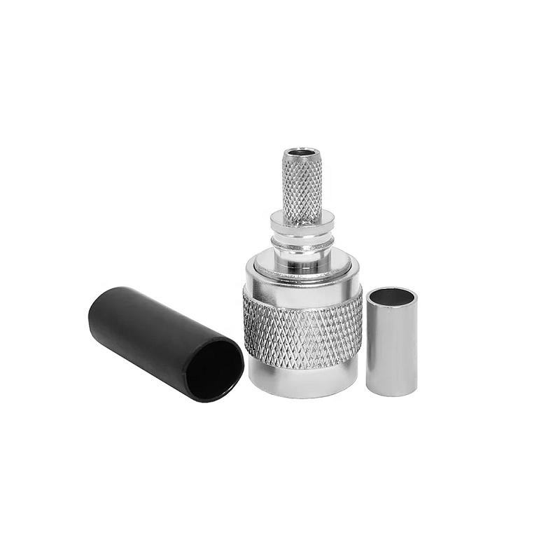
Selecting the proper interconnect within high-frequency signal systems directly dictates system power efficiency, signal clarity, and overall mechanical durability. Navigating the sheer variety of available interface designs can prove daunting when balancing performance targets, physical constraints, and environmental exposure. A thorough coaxial connector overview helps clarify which interface best suits specific operational demands, keeping signal attenuation low and impedance stable across diverse operating bands.
Evaluating key operational parameters before selecting specific rf coaxial connector types ensures optimal performance under real-world conditions. Operating frequency caps, power dissipation limits, characteristic impedance matching, coupling mechanisms, and weatherproofing must all align with equipment specifications. Using a structured RF connector guide prevents unexpected signal degradation, impedance mismatches, and premature mechanical wear across critical communication paths.
Choosing between distinct RF interface types requires evaluating several core performance variables:
Different applications call for specific mechanical geometries and electrical parameters to balance physical footprint against high-frequency performance:
| Connector Interface Type | Max Frequency Cap | Primary Coupling Mechanism | Power Rating | Typical Field Applications |
|---|---|---|---|---|
| SMA Interface | DC to 18 GHz (Precision: 26.5 GHz) | 1/4-36 Threaded Coupling | Low to Moderate | Test equipment, microwave modules, compact IoT |
| BNC Interface | DC to 4 GHz (50Ω) / DC to 2 GHz (75Ω) | Quarter-Turn Bayonet Lock | Moderate | Lab oscilloscopes, broadcast video, legacy telecom |
| TNC Interface | DC to 18 GHz | 7/16-28 Threaded Coupling | Moderate to High | Cellular base stations, avionics, high-vibration gear |
| N-Type Interface | DC to 11 GHz (Precision: 18 GHz) | 5/8-24 Threaded Coupling | High | Wireless infrastructure, outdoor antennas, radars |
| 7/16 DIN Interface | DC to 7.5 GHz | Heavy-Duty Threaded Coupling | Very High | 4G/5G macro cell towers, broadcast transmitters |
| UHF (PL-259) Interface | DC to 300 MHz | Threaded Coupling | High | Amateur HF radio, CB rigs, marine communications |
| MCX / MMCX Interfaces | DC to 6 GHz | Snap-On Push Coupling | Low | Internal GPS boards, compact wireless modules |
When evaluating aerial connector types mounted directly to outdoor antennas, tower rigs, or remote telemetry units, mechanical ruggedness and moisture ingress protection become paramount.
Selecting weatherized variants among these aerial connector types stops moisture wicking along shield braids, protecting expensive tower electronics from water damage.
During a multi-technology communications tower retrofit, installation teams managed equipment requiring five distinct rf coaxial connector types across a single rack footprint.
The cellular macro base station relied on high-power 7/16 DIN fittings, the microwave backhaul dish utilized precision N-type interfaces, the internal GPS timing receiver fed through a compact SMA jack, bench monitoring gear connected via BNC ports, and two-way radio equipment engaged TNC connectors. By establishing centralized adapter panels and standardized jumper harnesses, the team simplified cable management, minimized port strain, and maintained low insertion loss across all frequency bands.
Avoiding frequent specification pitfalls ensures long system service life and low signal reflection:
Delivering high-performance RF interconnects demands strict CNC machining tolerances, advanced plating techniques, and comprehensive high-frequency testing. Minor variations in center contact alignment or dielectric purity can degrade return loss performance across microwave frequencies.
Worldpeak addresses these critical industrial requirements through automated precision manufacturing, advanced surface plating, and complete RF characterization testing. Offering a comprehensive catalog of rf coaxial connector types—including precision SMA, BNC, TNC, N-Type, 7/16 DIN, MCX, and MMCX configurations—as well as specialized adapters for all commercial aerial connector types, Worldpeak utilizes premium materials such as gold-plated beryllium copper contacts, passivated stainless steel, and high-purity PTFE dielectrics.
Every Worldpeak component undergoes 100% automated continuity and VSWR verification to guarantee electrical stability and mechanical reliability. Whether building next-generation 5G cellular infrastructure, assembling aerospace telemetry systems, or sourcing high-volume industrial interconnects, partnering with an established manufacturer like Worldpeak ensures low transmission loss, thermal resilience, and reliable global supply chain delivery.

2026/09/24
Choose a 7 16 connector for high-power RF: compare DIN and Type N, protect PIM margin, and apply field installation checks.

2026/09/24
Compare TNC connector types, specs and applications, including RP-TNC, bulkhead options, vibration performance and adapter selection.

2026/09/24
Understand MMCX connector basics, RF limits, and how to choose the right coaxial interface for compact systems.

2026/09/24
Understand RP-SMA connector polarity, mating rules, frequency checks, and OEM termination options for reliable RF builds.

2026/09/24
Choose the right bnc male connector for RF, CCTV and test systems with clear 50Ω vs 75Ω, type and installation guidance.

2026/09/24
Compare LMR400 specs, cable loss, uses, connectors and RG8/RG213 alternatives with a practical RF loss-budget method.