EN
EN

tnc-male-to-tnc-male-lightning-arrester---dc---3-ghz, tnc-male-to-tnc-male-lightning-arrester---dc---3-ghz, /rf-lightning-arrester
EN
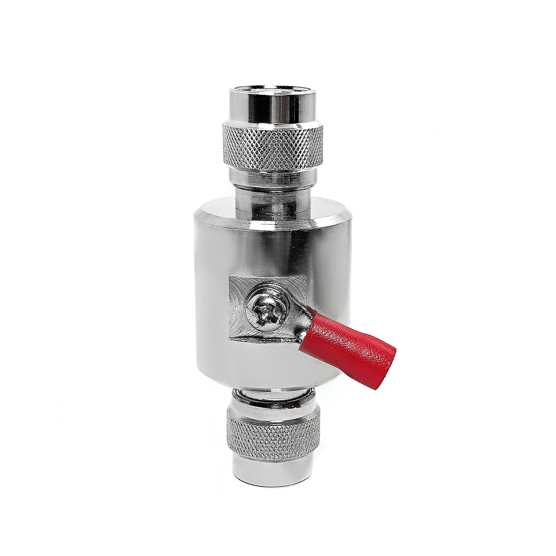
This TNC Male to TNC Male lightning arrester is a GDT based RF surge protector designed for DC - 3 GHz operation. It sits in the transmission line between the antenna and the radio equipment, diverting lightning-induced transients to ground before they reach the sensitive front end. The 50 ohm design holds insertion loss at 0.2 dB with a VSWR of 1.25 or better across the passband.
Request a Quote | Download Datasheet | Ask an Engineer
Product Overview
This inline TNC Male to TNC Male lightning arrester is intended for 50 ohm coaxial connections from DC to 3 GHz. A replaceable 90 V gas discharge tube, rated at 10 kA on the 8/20 us waveform, routes transient energy toward the grounding lug. During normal service, the RF path remains high impedance at the element and lists 0.2 dB insertion loss.
Core Trade-off: The replaceable GDT element provides a low-capacitance signal path for the stated application. Compared with diode devices, its triggering threshold is higher, while the configuration is suitable for compatible antenna-line installations.
Protection Mechanism and Construction
Reference Technical Specifications
The following values are reference information for this TNC Male to TNC Male lightning arrester and should be checked against the final production configuration.
Technical item |
Listed value |
Reference note |
RF connector pair |
TNC Male to TNC Male |
Compatible RF termination |
Installation form |
Inline |
Housing arrangement |
Nominal resistance |
50 ohm |
Line resistance |
Operating band |
DC - 3 GHz |
Supported spectrum |
Signal attenuation |
0.2 dB |
Within stated band |
VSWR |
1.25 |
Maximum |
CW power reference |
150 W |
Reference CW condition |
Arrester element |
90 V |
GDT element |
Transient current |
10 kA (8/20 us) |
8/20 us test wave |
Earth connection |
Ring terminal |
M4 earth-lead lug |
Housing composition |
Machined brass |
Protective surface plating |
Unit mass |
121 g |
Reference mass |
Typical use |
Aviation radio and outdoor comms, marine radio |
Intended use context |
These figures are reference values for this protection family and require confirmation against the final production configuration.
Engineering Comparison
Applications
Installation and Grounding Notes
OEM and B2B Support
FAQ
Q: How often does the gas discharge tube need replacement?
A: The 90 V tube has a 10 kA rating on the 8/20 us waveform. Following a major surge event, test the element; replace it if leakage is present or if it does not pass the hold-off test, without replacing the entire unit.
Q: Will this TNC Male to TNC Male lightning arrester affect my DC - 3 GHz signal?
A: The stated passband values are 0.2 dB insertion loss and VSWR up to 1.25, providing a low-impact path for applicable antenna-line installations.
Q: Can I use this arrester indoors?
A: Yes. It may be installed at the equipment end of a cable run as well as at an entry point where an additional protection stage is required. A TNC Male to TNC Male lightning arrester should be selected for compatible TNC cable assemblies and grounding access. This RF surge protector supports the listed 50 ohm line arrangement. The stated 3 GHz coaxial lightning protection range applies to compatible RF paths. For aviation radio and outdoor comms surge protection, position the unit at the relevant cable entry. A TNC Male to TNC Male lightning arrester should be checked against the final production configuration. This RF surge protector requires an appropriate earth connection. Before installation, review the cable route, the selected connector interfaces, the available bonding point, and the environment surrounding the equipment. Keep the protective device accessible for inspection and ensure that the enclosure, panel opening, or cable-entry location supports the selected inline arrangement. Confirm that the earth conductor follows the site grounding practice and that the connection remains secure after routine maintenance. At exposed locations, consider the condition of weatherproofing, cable support, strain relief, and any enclosure sealing used around the RF path. During commissioning, inspect connector engagement, verify the continuity of the grounding path, and record the installed location for service reference. After a significant electrical event, examine the protection element and associated cable interfaces before returning the system to normal operation. These steps help align the installed assembly with the intended equipment layout without changing the listed electrical reference values. The installation review can also include the cable-entry route, available service clearance, physical support of the cable, and the location of the associated radio equipment. Identify any points where the coaxial line changes direction, enters a cabinet, passes through a panel, or is exposed to moisture. Review whether the selected mounting location allows the grounding conductor to remain direct and practical while avoiding unnecessary bends or unsupported sections. Confirm that there is adequate room to connect, inspect, and maintain the TNC interfaces without placing strain on the cable assembly. Where the device is located near other equipment, keep the installation arrangement consistent with the operating and maintenance requirements of the site. Document the selected mounting point, cable orientation, and earth connection so that future inspection can use the same reference. Before system handover, verify that all mechanical connections are secure, the protective housing is accessible, and any outdoor sealing is complete. If the radio installation changes, reassess the cable path and grounding arrangement before moving or replacing the device. This planning information is intended to support a careful installation review and does not replace the final product documentation or site-specific electrical requirements.